Elemental geometric properties
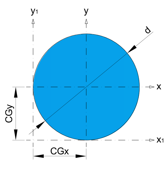
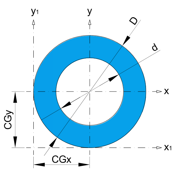
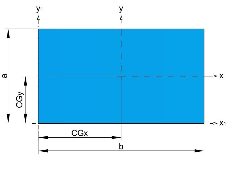
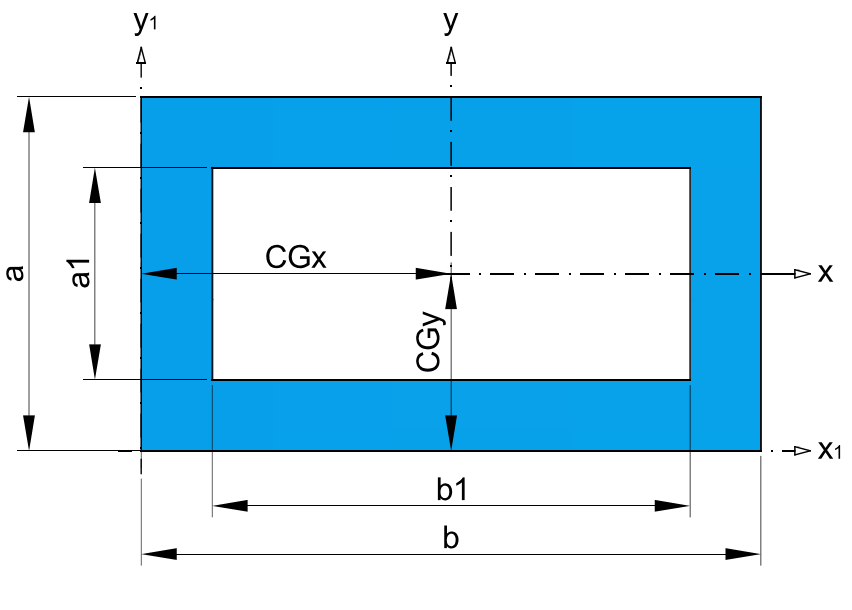
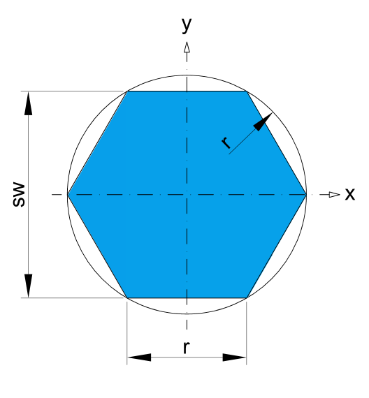


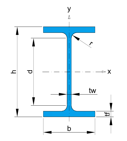
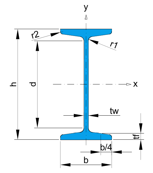
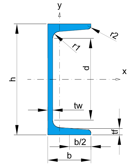
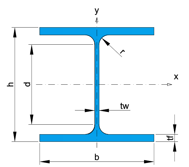
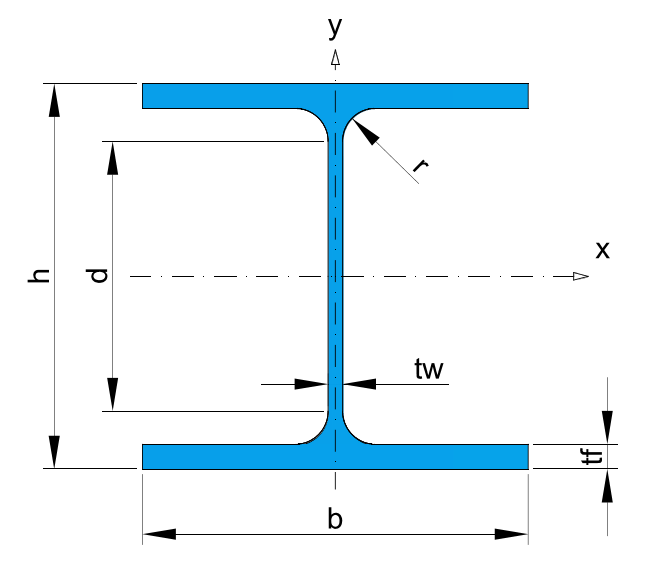
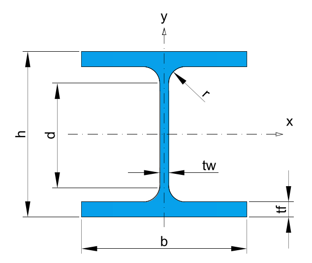
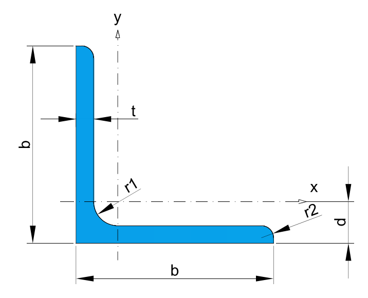
* Recommended dimensions.
Second moment of area,
Also known as moment of inertia of plane area, area moment of inertia, or second area moment, is a geometrical property of an area which reflects how its points are distributed with regard to an arbitrary axis. The second moment of area is typically denoted with either an I for an axis that lies in the plane or with a J for an axis perpendicular to the plane.
In both cases, it is calculated with a multiple integral over the object in question. Its dimension is L (length) to the fourth power. Its unit of dimension when working with the International System of Units is meters to the fourth power, m4, or inches to the fourth power, in4, when working in the Imperial System of Units.
In structural engineering, the second moment of area of a beam is an important property used in the calculation of the beam’s deflection and the calculation of stress caused by a moment applied to the beam.
The planar second moment of area provides insight into a beam’s resistance to bending due to an applied moment, force, or distributed load perpendicular to its neutral axis, as a function of its shape.
The polar second moment of area provides insight into a beam’s resistance to torsional deflection, due to an applied moment parallel to its cross-section, as a function of its shape. This resistance to deflection or torsion is only a function of shape, and not due to a beam’s material stiffness, or Elastic Modulus.
Elastic modulus
Also known as section modulus. It is termed as the ratio of second moment of area and distance from N.A (Neutral axis) to the extreme fiber. Also it is the measure of strength of given member. The stress in the outermost section of beam is computed with the help of section modulus. It is indicated by W.
Section modulus is indicated as follows:
Here, I is “moment of inertia” and y is distance from “neutral axis” to top or bottom of fiber.
Unit of a “section modulus” is in.3(mm3).
Section modulus depends only on the cross section shape of the beam. Cross section shapes like rectangular, square, circular, Isection and T, composite section etc.
For symmetric sections, the value of “section modulus” is for both above and below of centroid of the fiber.
An asymmetric section has two values for top and bottom of the fiber due to different distance from centroid to the top and bottom of the material, the maximum “section modulus” is W max and the minimum section modulus is W min.
Importance:
• It is significant for beam and flexural member design.
• More the section modulus, more the member is resistant to bending of the beam.
• It is easier to calculate stresses in beam and an exact measure of strength of steel.
• If two beams are made of same material and comparing the “section modulus” of two beams, the beam with bigger section modulus will be tougher and more capable to withstand larger loads.
Radius of Gyration
“Radius of gyration” is indicated by,
Here, I is the moment of inertia, and A is area of cross section.
Unit of “radius of gyration” is mm.
Radius of gyration about x, y and z axis is articulated as,
Here, Ix,Iy are the moment of inertia of the x and y axis, J is the polar moment of inertia about z axis.
Importance of “radius of gyration”:
• Radius of gyration is valuable in calculating buckling load of a compression member or a beam.
• Distribution of strength among the column cross section is obtained by radius of gyration.
• It helps to compare the behavior of different structural shape during compression.
• Smaller value of radius of gyration is utilized in structural analysis.
• The maximum compressive load the column can withstand is obtained when the column fails due to buckling.
• Smaller value of “radius of gyration” or least moment of inertia shows that the axis which the column buckles.