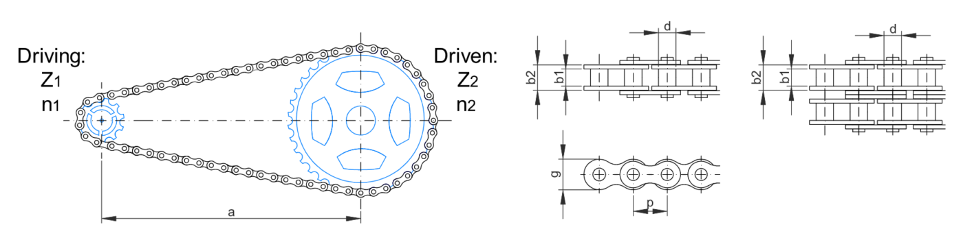
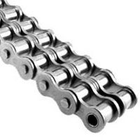
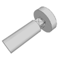
Roller Chain


Nductile ≥ max(N1, N2, N3) ; based on yield strength
Nbrittle ≥ max(N1, N2, N3) ; based on ultimate strength
N = N1 . N2
N1 = f(A, B, C), from the first table
N2 = f(D, E) , from the second table
Parameters:
A Quality of materials, workmanship, maintenance and inspection
B Control over applied loads
C Accuracy of stress analysis, experimental data, or experience with similar parts
D Danger to people
E Economic impact
The transition from engineering model to reality is usually facilitated by including a factor of safety in the design to accommodate uncertainly in material properties and the design process, the consequences of failure, risk to people and degree of characterization of and control over the service environment.
Safety factor is a simple ratio that is intended to be greater than 1.
Safety factors for ductile materials are based on yield strength. Safety factors for brittle materials are based on ultimate strength and are twice the recommended values for ductile materials. Safety factors for primarily cyclic loading are based on endurance limit. Impact loads require a safety factor of at least 2 multiplied by an impact factor from 1.1 to 2.
The factor safety is often specified in a design code or standard.
Factor safety is affected by:
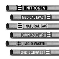
DIN 2403 defines the identification of pipes according to the fluid conveyed.
The pipelines shall be clearly idetified by labels specifying the nature of the fluid conveyed with labels or adhesive labels. The size of the labels shall be selected fron DIN 825 Part 1.
Standards and other documents referred to:
DIN 825 Part 1 Dimensions of nameplates; square and rectangular nameplates
DIN 1304 Symbols for formulae
DIN 6164 Part1 DIN colour chart
DIN 25400 Warning symbol for ionizing radiation
RAL 840 HR Colour register
ANSI/ASME A13.1 Pipe identification standard used in the United States
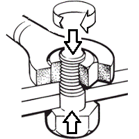
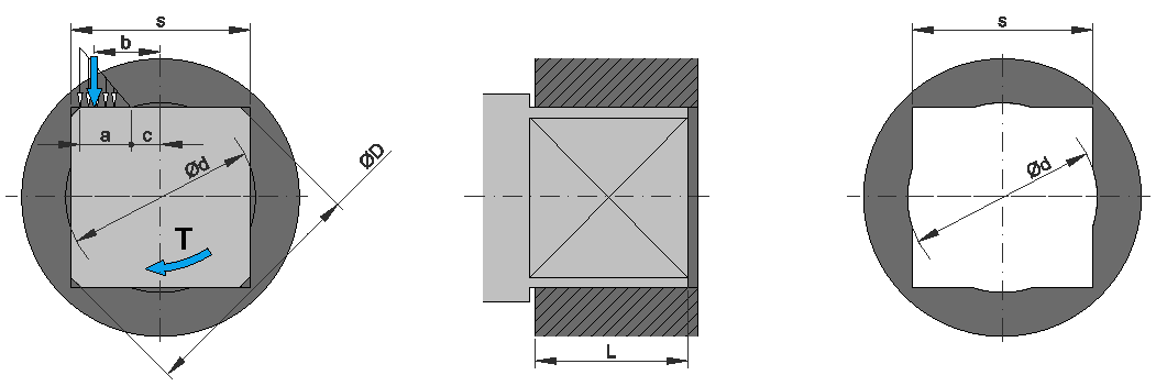
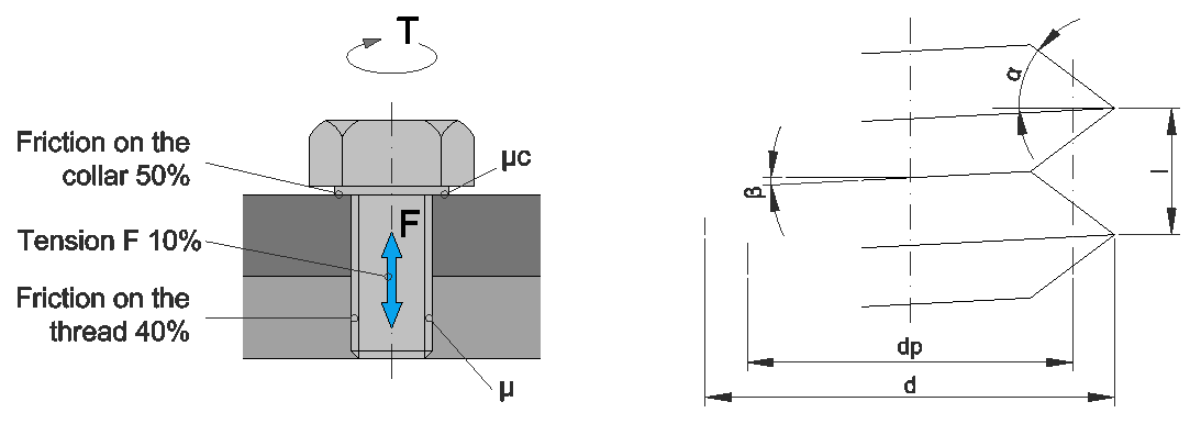
The torque required to tighten the bolt:
Where:
T: Torque (N.m)
K: Torque coefficient
F: Axial preload force (N)
d: Nominal bolt diameter (mm)
The torque coefficient:
Where:
l: Lead (mm)
α: Half angle of the screw thread (°)
d: Nominal bolt diameter (mm)
µ: Thread friction coefficient
µc: Collar friction coefficient
Common torque coefficient values for µ=µc=0.15:
| Bolt condition | K |
| Non plated black finish steel bolts | 0.3 |
| Mild steel bolts | 0.2 |
| Zinc plated steel bolts | 0.2 |
| Lubricated steel bolts | 0.18 |
| Cadmium plated steel bolts | 0.16 |
| With bowman anti-seize | 0.12 |
| With bowman-grip nuts | 0.09 |
It is estimated that roughly 90% of the input energy is lost in overcoming the mating friction under the head (collar) and between the thread or nut and its mating threads. Consequently only the remaining 10% of input energy is turned into bolt stretch.
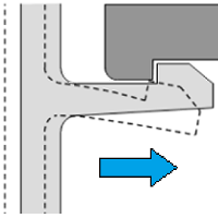
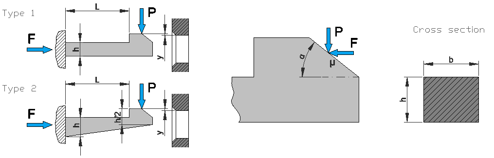
This calculation is for a snap-fitting hook of rectangular cross section.There are two types which can be choosen for the calculation. Type 1 is a snap-fitting hook of a constant rectangular cross section and Type 2 is a snap-fitting hook of rectangular cross section with a constant decrease in thickness from h at the root to h/2 at the end of the hook. Young modulus and Yield strength of the material have to be choosen. The Deflection Force is the force required to bend the arm the value of the introduced deflection (y). Introducing the friction coefficient of the material and the angle of the arm according with the shape represented in picture, the mating force is calculated. This is the force required for introducing the snap-fitting hook. The calculus allows to ensure that the yield strength of the material won’t be exceeded as long as the safety coeficient is higher that 1. This calculation is an approximation because of we are only taking into account the shear due to bending.