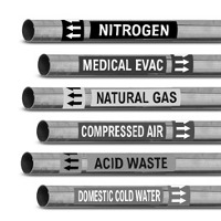
Colours for the identification of pipelines
DIN 2403 defines the identification of pipes according to the fluid conveyed.
The pipelines shall be clearly idetified by labels specifying the nature of the fluid conveyed with labels or adhesive labels. The size of the labels shall be selected fron DIN 825 Part 1.
Standards and other documents referred to:
DIN 825 Part 1 Dimensions of nameplates; square and rectangular nameplates
DIN 1304 Symbols for formulae
DIN 6164 Part1 DIN colour chart
DIN 25400 Warning symbol for ionizing radiation
RAL 840 HR Colour register
ANSI/ASME A13.1 Pipe identification standard used in the United States