Category Archives: Technical drawing

Thread identification guide

Thread identification guide

STEP 1

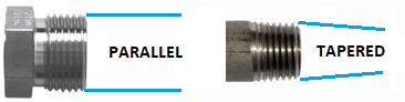
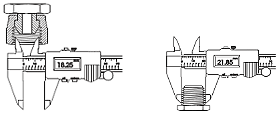
Determine if the thread is tapered or parallel/straight.

Measure the thread with a caliper at the beginning and the end. If the diameters increase for a male end or decrease for a female end, the thread is tapered. If it is the same value the thread is straight/parallel.

STEP 2

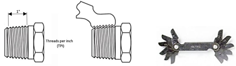
Determine the thread size and type. Imperial sizes are normally common fractions ¼”=0.25”.

Measure the outside diameter OD for male and inside ID for female threads.

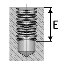
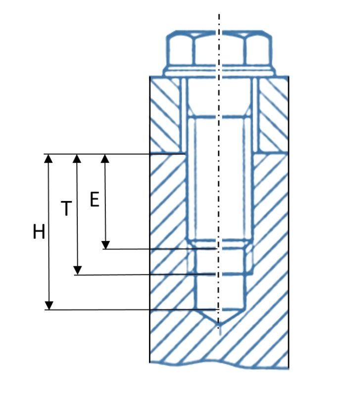
If the thread is tapered measure the diameter of 4th or 5th full thread.

The diameter measurement obtained in this step may not be exactly the same as the listed nominal size for the given thread. This variation is due to manufacturing tolerances.

STEP 3

Determine the pitch for metric or the amount of threads per inch (T.P.I) for imperial sizes.

In both cases Thread pitch gauges can be used.

TPI 28 27 24 20 19 18  16  14  12 11.5 11 8
Thread pitch (mm) 0.91 0.94 1.06 1.27  1.34  1.4  1.59  1.81  2.12 2.21 2.31 3.18

Check for any markings on fitting or equipment which may be a clue to thread type. Country of origin may provide a clue.

Europe (DIN,BSP), America (NPT, JIC, UNO, ORFS), UK/Australia (BSP), Japan (JIS).

www.caetool.com

Thread runouts

Thread runouts for metric ISO threads

DIN 76-1

For fine threads the dimension of the thread runout is chosen according to the pitch P.

1)As a general rule, apply if no other entries are given.

2)IApply if a shorter thread runout is necessary.

3)Apply if a longer thread runout is necessary.

www.caetool.com

Tool dimensions

Tool dimensions

ISO 1085
DIN 3110

ScrewSWDBCL
M36163.85.4100
M47184.26.3100
M58194.87.2110
M6102359110
M813327.811.7110
M10174010.215.3140
M12194411.417.1160
M14224913.219.8170
M16245414.421.6180
M18276016.224.3190
M2030661827200
M22327019.228.8210
M24367821.632.4220

ISO 2936
DIN 911

ScrewsAB
M32.55618
M436320
M547025
M658028
M869032
M10810036
M121011240
M141212545
M161414056
M181414056
M201716063
M221716063
M241918070
ScrewSWDBAL
M3691023104
M47111123116
M58131327125
M610151535160
M813191945188
M1017252452255
M1219272960285
M1422313170314
M1624343475342
M1827384080375
M2030424385400
M2232454590420
M2436505295440

www.caetool.com

Countersinks

Countersinks

Countersink for DIN 7991, DIN 7987, DIN 7988, DIN 87, DIN 88, DIN 7513, DIN 7516

DIN 75
FORM B

This Calculator provides the values of  the countersink for next countersunk head screws :
DIN 87, form B
DIN 7987, form B
DIN 7991, form B
DIN 88, form B
DIN 7988, form B
DIN 7514 , form D and E from M6
DIN 7516, form B and C

Countersink for DIN 912

DIN 75

Countersink for DIN 84

DIN 75

www.caetool.com

Minimum thread engagement depth

Minimum thread engagement depth

The table shows, for differents materials, the minimum engagement depth of a threaded hole (L) to enable the screw fails before the thread of the hole.

So, it is needed to define previously, the characteristics ot the screw:
– ISO Standard Thread (available from M1 to M36)
– Property class
– Thread pitch (fine or coarse)

Finally, the table also shows, the rest of dimensions that the hole should have, according to DIN 77 norm:
– Surplus thread length
– Thread total length
– Thread runout
– Hole total length

If the result of the cell is a “-” (dash), means that the holed material resistance is lower than the screw material, and in consequence, the thread of the hole will fail before the screw.