Cylinder air consumption
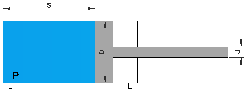
This calculator is valid for simple and double effect. For simple effect the value provide by the calculator has to be divided by 2.
Leakage is not taken into the calculator.

This calculator is valid for simple and double effect. For simple effect the value provide by the calculator has to be divided by 2.
Leakage is not taken into the calculator.

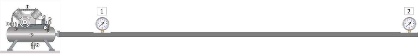
The length of the pipe is from the compressor to the farthest point.
– For a closed ring the diameter can be reduced by 29%.
– For pressed stainless steel pipe reduce the diameter by 6%
– For aluminum pipes reduce the diameter by 9%.
– Frequent loss of pressure 0.1-0.3 bar
– A maximum pressure loss of 0.1 bar is recommended.
A loss of pressure of 0.4 bar or higher is not profitable.
0.4 bar of pressure loss supposes an additional 3% of consumption.
Compressed Air Pipe Lines – Recommended Size Engineering Toolbox
TLV A steam specialist company
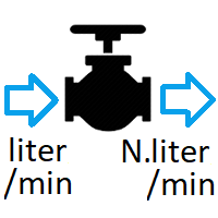
ACTUAL FLOW RATE is the actual volume of fluid that passes a given point in a pipe per unit time e.g. l/min. This can be a useful measurement to have, however since gases are compressible the volume of gas will vary depending on its pressure and temperature. Therefore it is generally more useful to have a flow rate referenced to a set pressure and temperature, hence the use of Standard flow rate, and Normal flow rate.
These units are corrections applied to an actual flow measurement based on a given temperature and pressure. The correction is applied using the ideal gas law.
This allows us to compare different flows existing at different flowing conditions of pressure and temperature.
However, the problem with Standard and Normal conditions is that they have several different definitions depending on the industry you work in, and in the country you work.
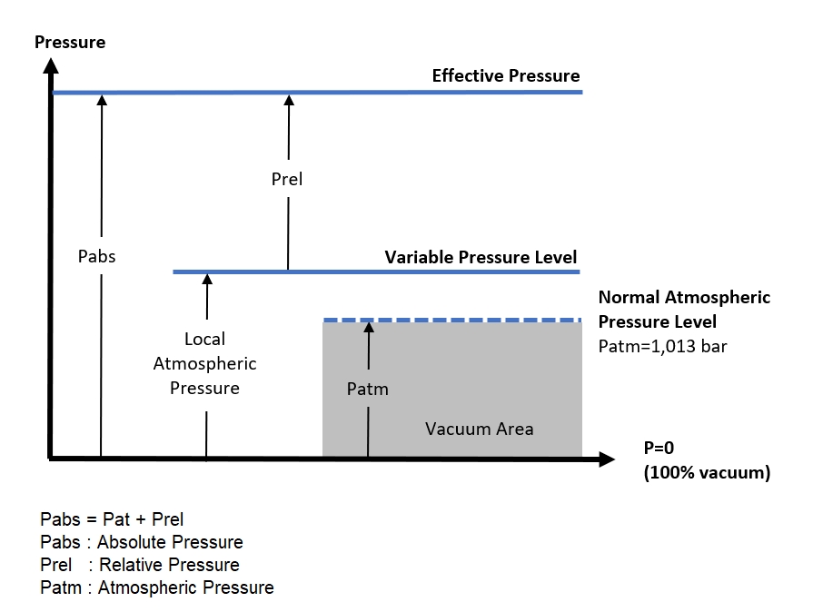
NORMAL CONDITIONS FOR TEMPERATURE AND PRESSURE (NCTP, common in Europe)
Commonly used as a standard condition for testing and documentation of fan capacities
NTP is defined as a temperature of 20 °C (293.15 K, 68 °F) and an absolute pressure of 1 atm (1,013 bar, 101,325 kPa).
Flow Rate Units e.g.:
Normal litre per minute (NLPM)
STANDARD CONDITIONS FOR TEMPERATURE AND PRESSURE (SCTP, common in the United States)
important for the measurements and documentation of chemical and physical processes
Until 1982, STP was defined as a temperature of 273.15 K (0 °C, 32 °F) and an absolute pressure of 101.325 kPa (1 atm).
Since 1982, STP is defined as a temperature of 273.15 K (0 °C, 32 °F) and an absolute pressure of 100 kPa (1 bar).
Flow Rate Units e.g.:
Standard litre per minute (SLM or SLPM)
Standard cubic feet per minute (SCFM)
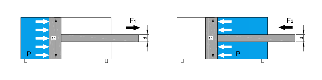
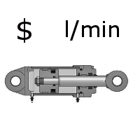
The calculator provides the pull and push forces in a cylinder when is aplied a pressure in a single acting cylinder and in a doble acting cylinder.