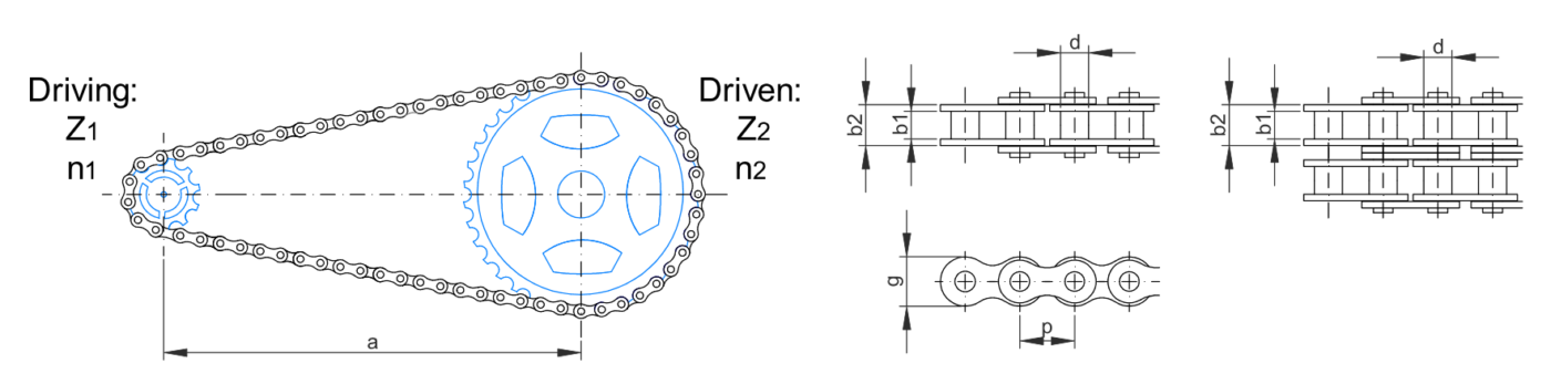
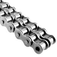
Roller Chain


| TYPE | EN MATERIAL NUMBER | OTHER MATERIAL DESIGNATION | FORMING PROCESS | MODULUS OF ELASTICITY E (MPa) | MODULUS OF RIGIDITY G (MPa) | DENSITY ρ (kg/m3) | POISSON'S RATIO ν | YIELD STRENGTH Re; Rp0,2 (MPa) | TENSILE STRENGTH Rm (MPa) | COMMENTS |
|---|---|---|---|---|---|---|---|---|---|---|
| CARBON STEEL | 1.0045 | |||||||||
| STAINLESS STEEL | 1.4310 | 212000 | 8030 | 0.3 | 205 | 515 | ||||
| STAINLESS STEEL | 1.4305 | 193000 | 8000 | 0.25 | 240 | 620 | ||||
| STAINLESS STEEL | 1.4301 | 193000 | 7900 | 0.29 | 210 | 505 | ||||
| STAINLESS STEEL | 1.4307 | 193000 | 7900 | 0.29 | 210 | 505 | ||||
| STAINLESS STEEL | 1.4401 | 193000 | 8000 | 0.3 | 240 | 550 | ||||
| STAINLESS STEEL | 1.4435 | 193000 | 8000 | 0.3 | 240 | 550 | ||||
| BRONZE | 103421 | 8850 | 0.34 | 110 | 250 | Type CUSN12 - B12 | ||||
| POM C (DELRIN) | 3000 | 1390 | 63 | 115 | ||||||
| POLICARBONATE | 2200 | 1200 | 0.37 | 65-35 | 65 | |||||
| PMMA (METHACRYLATE) | 3300 | 1180 | 0.45 | 72 | ||||||
| TITANIUM | 115000 | 4730 | 830 | 900 | ||||||
| STRUCTURAL STEEL A36 | 1.0117 | 200000 | 77200 | 7860 | 250 | 400 | ||||
| ALUMINUM 1100-H14 | 70000 | 26000 | 2710 | 0.33 | 95 | 110 | 99% Al | |||
| ALUMINUM 2014-T6 | 75000 | 27000 | 2800 | 400 | 455 | |||||
| ALUMINUM 2024-T4 | 73000 | 2800 | 325 | 470 | ||||||
| ALUMINUM 5456-H116 | 72000 | 2630 | 230 | 315 | ||||||
| ALUMINUM 6061-T6 | 70000 | 26000 | 2710 | 0.33 | 240 | 260 | ||||
| ALUMINUM 7075-T6 | 72000 | 28000 | 2800 | 500 | 570 | |||||
| GLASS | 65000 | 4100 | 2190 | 98% silica |
| DIN NUMBER REFERENCE | DESCRIPTION______________________________________________________________________________ | DIN replacement | Other org |
|---|---|---|---|
| DIN 1 | Cone Pins, untempered | DIN EN 22339 | ISO 2339 |
| DIN 3 | Standard measurements | ||
| DIN 5 | Technical drawings - Axonometric projections, Isometric projection | DIN ISO 5456-1, DIN ISO 5456-2, | |
| DIN 5-10 | Technical drawings - projections, terms | DIN ISO 10209-2 | ISO 10209-2 |
| DIN 6 | Projection displays in Normal, views and special presentations | DIN ISO 128, DIN EN ISO 128 | ISO 128 |
| DIN 7 | Parallel Pins | DIN EN ISO 2338 | ISO 2338 |
| DIN 11 | Whitworth pipe threads 1/4"-6" Thread diameter, sizes, teaching information | ||
| DIN 13-1 | ISO general purpose metric screw threads - Part 1: Nominal sizes for coarse pitch threads; nominal diameter from 1 mm to 68 mm | ||
| DIN 13-2 | ISO general purpose metric screw threads - Part 2: Nominal sizes for 0,2 mm, 0,25 mm and 0,35 mm fine pitch threads; nominal diameter from 1 mm to 50 mm | ||
| DIN 13-3 | ISO general purpose metric screw threads - Part 3: Nominal sizes for 0,5 mm fine pitch threads; nominal diameter from 3,5 mm to 90 mm | ||
| DIN 13-4 | ISO general purpose metric screw threads - Part 4: Nominal sizes for 0,75 mm fine pitch threads; nominal diameter from 5 mm to 110 mm | ||
| DIN 13-5 | ISO general purpose metric screw threads - Part 5: Nominal sizes for 1 mm and 1,25 mm fine pitch threads; nominal diameter from 7,5 mm to 200 mm | ||
| DIN 13-6 | ISO general purpose metric screw threads - Part 6: Nominal sizes for 1,5 mm fine pitch threads; nominal diameter from 12 mm to 300 mm | ||
| DIN 13-7 | ISO general purpose metric screw threads - Part 7: Nominal sizes for 2 mm fine pitch threads; nominal diameter from 17 mm to 300 mm | ||
| DIN 13-8 | ISO general purpose metric screw threads - Part 8: Nominal sizes for 3 mm fine pitch threads; nominal diameter from 28 mm to 300 mm | ||
| DIN 13-9 | ISO general purpose metric screw threads - Part 9: Nominal sizes for 4 mm fine pitch threads; nominal diameter from 40 mm to 300 mm | ||
| DIN 13-10 | ISO general purpose metric screw threads - Part 10: Nominal sizes for 6 mm fine pitch threads; nominal diameter from 70 mm to 500 mm | ||
| DIN 13-11 | ISO general purpose metric screw threads - Part 11: Nominal sizes for 8 mm fine pitch threads; nominal diameter from 130 mm to 1000 mm | ||
| DIN 13-12 | ISO general purpose metric screw threads - Part 12: 1 to 300 mm diameter coarse and fine pitch threads Selected diameters and pitches | ||
| DIN 13-13 | ISO general purpose metric screw threads - Part 13: Selected sizes for screws, bolts and nuts from 1 to 52 mm screw thread diameter and limits of sizes | ||
| DIN 13-19 | ISO general purpose metric screw threads - Part 19: Nominal profiles | ||
| DIN 13-20 | ISO general purpose metric screw threads - Part 20: Limits of sizes for coarse pitch threads with the preferred tolerance classes; nominal sizes from 1 mm to 68 mm | ||
| DIN 13-21 | ISO general purpose metric screw threads - Part 21: Limits of sizes for fine pitch threads with the preferred tolerance classes; Nominal diameter from 1 mm to 24,5 mm | ||
| DIN 13-22 | ISO general purpose metric screw threads - Part 22: Limits of sizes for fine pitch threads with the preferred tolerance classes; Nominal diameter from 25 mm to 52 mm | ||
| DIN 13-23 | ISO general purpose metric screw threads - Part 23: Limits of sizes for fine pitch threads with the preferred tolerance classes; Nominal diameter from 53 mm to 110 mm | ||
| DIN 13-24 | ISO general purpose metric screw threads - Part 24: Limits of sizes for fine pitch threads with the preferred tolerance classes; Nominal diameter from 112 mm to 180 mm | ||
| DIN 13-25 | ISO general purpose metric screw threads - Part 25: Limits of sizes for fine pitch threads with the preferred tolerance classes; Nominal diameter from 182 mm to 250 mm | ||
| DIN 13-26 | ISO general purpose metric screw threads - Part 26: Limits of sizes for fine pitch threads with the preferred tolerance classes; Nominal diameter from 252 mm to 1000 mm | ||
| DIN 13-28 | ISO general purpose metric screw threads - Part 28: Coarse and Fine Screw Threads from 1 to 250 mm Screw Thread Diameter; Root Cross-sections, Tensile Stress Cross-sections and Pitch Angles | ||
| DIN 13-50 | ISO general purpose metric screw threads - Part 50: Combination of tolerance classes for formed internal screw threads | ||
| DIN 13-51 | ISO general purpose metric screw threads - Part 51: External screw threads for transition fits (former: screw threads for interference fit); tolerances, limit deviations, limits of sizes | ||
| DIN 13-52 | ISO general purpose metric screw threads - Part 52: Multi-start thread tolerances and deviation of profile | ||
| DIN 15-2 | Technical drawings; lines; general application | DIN ISO 128-24 | |
| DIN 16 | Oblique Standard Typeface for Drawings | ||
| DIN 17 | Upright Standard Typeface for Drawings | ||
| DIN 38 | Plain bearings; bearing metal lining for thick-walled multilayer plain bearings | ||
| DIN 74 | Countersinks for countersunk head screws (except screws with DIN EN 27721 head) | ||
| DIN 76-1 | Thread run-outs and thread undercuts for ISO metric threads in accordance with DIN 13-1 | ||
| DIN 76-2 | Thread run-outs and thread undercuts for pipe threads conforming to ISO 228 part 1 | ||
| DIN 76-3 | Runouts, Undercuts for Trapezoidal Threads, Buttress Threads and Knuckle Threads and other Threads of Coarse Pitch | ||
| DIN 78 | Protrusions of bolt ends | DIN EN ISO 4753 (governs thread ends for bolts assembled with hexagon slotted nuts) | ISO 4753 |
| DIN 84 | Product grade A slotted cheese head screws | DIN EN ISO 1207 | ISO 1207 |
| DIN 85 | Product grade A slotted pan head screws | DIN EN ISO 1580 | ISO 1580 |
| DIN 88 | Product slotted oval head countersunk machine screws | ISO 2010-1983[1] | |
| DIN 93 | Tab washers with long tab | ||
| DIN 94 | Split pins | DIN EN ISO 1234 | ISO 1234 |
| DIN 95 | Slotted Raised Countersunk (Oval) Head Wood Screws | ||
| DIN 96 | Slotted Round Head Wood Screws | ||
| DIN 101 | Rivets - Technical specifications | ||
| DIN 103-1 | ISO Metric Trapezoidal Screw Thread; Profiles | ||
| DIN 103-2 | ISO Metric Trapezoidal Screw Thread; General Plan | ||
| DIN 103-3 | ISO Metric Trapezoidal Screw Thread; Allowances and Tolerances for Trapezoidal Screw Threads of General Purpose | ||
| DIN 103-4 | ISO Metric Trapezoidal Screw Thread; Nominal Dimensions | ||
| DIN 103-5 | ISO Metric Trapezoidal Screw Threads; Limiting Sizes for Nut Threads from 8 to 100 mm Nominal Diameter | ||
| DIN 103-6 | ISO Metric Trapezoidal Screw Threads; Limiting Sizes for Nut Threads from 105 to 300 mm Nominal Diameter | ||
| DIN 103-7 | ISO Metric Trapezoidal Screw Threads; Limiting Sizes for Bolt Threads from 8 to 100 mm Nominal Diameter | ||
| DIN 103-8 | ISO Metric Trapezoidal Screw Threads; Limiting Sizes for Bolt Threads from 105 to 300 mm Nominal Diameter | ||
| DIN 103-9 | ISO metric trapezoidal screw threads; gauging of external and internal threads; gauge dimensions and design features | ||
| DIN V 105-1 | Clay masonry units - Part 1: Solid and hollow bricks with density classes of 1,2 | DIN V 105-100, DIN EN 771-1 | EN 771-1 |
| DIN V 105-2 | Clay masonry units - Part 2: Solid and hollow bricks with density classes equal 1.0 | DIN V 105-100, DIN EN 771-1 | EN 771-1 |
| DIN 105-3 | Clay masonry units - Part 3: Tile and high strength-high-strength clinker | DIN V 105-100, DIN EN 771-1 | EN 771-1 |
| DIN 105-4 | Clay masonry units - Part 4: Ceramic bricks | DIN V 105-100, DIN EN 771-1, | |
| DIN EN 772-7 | EN 771-1, EN 772-7 | ||
| DIN 105-5 | Clay masonry units - Part 5: Lightweight long-hole brick and light long-hole brick panels | ||
| DIN V 105-6 | Clay masonry units - Part 6: High precision units | ||
| DIN V 105-100 | Clay masonry units - Part 100: Clay masonry units with specific properties | ||
| DIN 125 | Washers; medium type, primarily for hexagon bolts | DIN EN ISO 7089, | |
| DIN 125-1 | Product grade A washers - with a hardness up to 250 HV designed for use with hexagon head bolts and nuts | DIN EN ISO 7089, | |
| DIN 125-2 | Product grade A washers - with a hardness up to 300 HV designed for use with hexagon head bolts and nuts | DIN EN ISO 7089, | |
| DIN 126 | Product grade C washers - designed for use with hexagon head bolts and nut | DIN EN ISO 7091 | ISO 7091 |
| DIN 127 | Spring lock washers with square ends or tang ends | ||
| DIN 128 | Curved and wave spring lock washers | ||
| DIN 137 | Spring washers, curved or wave | DIN EN 137 | |
| DIN 174 | Bright Flat Steel; Dimensions, Permissible Variations, Weights | DIN EN 10278 | |
| DIN 175 | Polished round steel; Dimensions, Permissible deviations according to ISO tolerance zone h9 | DIN EN 10278 | |
| DIN 201 | Technical drawings; Hatchings; Representation of cutting edges and materials | DIN ISO 128-50 | ISO 128-50 |
| DIN 209 | Machine Reamers with Screwed-on Blades | ||
| DIN 267-1 | Fasteners - Part 1: Technical delivery conditions; General requirements | ISO 8992 | |
| DIN 267-2 | Fasteners - Part 2: Technical delivery conditions; Bolts, Screws, Nuts and Similar Threaded and Formed Parts; Types and Dimensional Accuracy | DIN EN ISO 4759-1 | ISO 4759-1 |
| DIN 267-3 | Fasteners - Part 3: Technical delivery conditions; Property classes for carbon steel and alloy steel bolts and screws; Conversion of property classes | DIN EN ISO 898-1 | ISO 898-1 |
| DIN 267-4 | Fasteners - Part 4: Technical delivery conditions; Property classes for nuts (previous classes) | DIN EN ISO 898-2 | ISO 898-2 |
| DIN 267-5 | Fasteners – Part 5: Technical delivery conditions; Acceptance inspection; modified version of ISO 3269, 1984 edition | DIN EN ISO 3269 | ISO 3269 |
| DIN 267-6 | Fasteners - Part 6: Technical delivery conditions; Designs and accuracy of measurement for product grade F | ||
| DIN 267-7 | Fasteners - Part 9: Technical delivery conditions; Bolts made of unalloyed or low-alloy steels | DIN EN ISO 898-1 | ISO 898-1 |
| DIN 267-9 | Fasteners - Part 9: Technical delivery conditions; Components with Electroplated Coatings | DIN EN ISO 4042 | ISO 4042 |
| DIN 267-10 | Fasteners - Part 10: Technical delivery conditions; Hot dip galvanized parts | DIN EN ISO 10684 | ISO 10684 |
| DIN 267-11 | Fasteners - Part 11: Technical delivery conditions (with additions to ISO 3506); Corrosion-resistant stainless steel fasteners | ||
| DIN 267-12 | Fasteners - Part 12: Technical delivery conditions; Self-tapping screws | DIN EN ISO 2702 | ISO 2702 |
| DIN 267-13 | Fasteners - Part 13: Technical delivery conditions; Components for Bolted Connections Made Mainly from Materials Exhibiting a High Impact Strength at Low Temperature or from Materials with a High Temperature Strength | ||
| DIN 267-15 | Fasteners - Part 15: Technical delivery conditions; Prevailing torque type nuts | DIN EN ISO 2320, | |
| DIN 267-18 | Fasteners - Part 18: Technical delivery conditions; Components made of Non-ferrous Metals | DIN EN 28839 | ISO 8839 |
| DIN 267-19 | Fasteners - Part 19: Technical delivery conditions; Surface discontinuities on bolts and screws | DIN EN ISO 26157-1, | |
| DIN 267-20 | Fasteners - Part 20: Technical delivery conditions; Surface discontinuities on nuts | DIN EN ISO 6157-2, | |
| DIN 267-21 | Fasteners - Part 21: Technical delivery conditions; Widening test on nuts | DIN EN ISO 6157-2, | |
| DIN 267-23 | Fasteners - Part 23: Technical delivery conditions; Property classes for nuts with fine thread (ISO classes) | DIN EN ISO 898-6 | ISO 898-6 |
| DIN 267-24 | Fasteners - Part 24: Technical delivery conditions; Property classes for nuts (Hardness classes) | ||
| DIN 267-25 | Fasteners - Part 25: Technical delivery conditions; Torsion testing of M1 to M10 bolts and screws | DIN EN 20898-7 | EN 20898-7 |
| DIN 267-26 | Fasteners - Part 26: Technical delivery conditions; Conical spring washers for bolt/nut assemblies | ||
| DIN 267-27 | Fasteners - Part 27: Technical specifications; Steel screws, bolts and studs with adhesive coating | ||
| DIN 267-28 | Fasteners - Part 28: Technical specifications; Steel screws, bolts and studs with locking coating | ||
| DIN 267-29 | Fasteners - Part 29: Technical specifications; Product grades for parts for bolted connections for use at temperatures ranging from -200 °C to +700 °C | ||
| DIN 267-30 | Fasteners - Part 30: Technical specifications; Metric thread rolling screws of property class 10.9 | ||
| DIN 276-1 | Building costs; Part 1: Building construction | ||
| DIN 276-2 | Building costs; Part 2: Classification of cost | ||
| DIN 276-3 | Building costs; Part 3: Ascertainment of cost | ||
| DIN 315 | Wing nuts with rounded wings | ||
| DIN 316 | Wing screws with rounded wings | ||
| DIN 317 | Drill drifts for taper shanks with drift tang | ||
| DIN 323-1 | Preferred Numbers and Series of Preferred Numbers; Basic Values, Calculated Values, Rounded Values | ||
| DIN 323-2 | Preferred Numbers and Series of Preferred Numbers; Introduction | ||
| DIN 332-1 | 60° centre holes; types R, A, B, and C | ||
| DIN 332-2 | Center holes 60° with thread for shaft ends for rotating electrical machines | ||
| DIN 332-4 | Centre holes for rail vehicles axles | ||
| DIN 332-7 | Machine tools; 60° centre holes; dimensioning | ||
| DIN 332-8 | Centre holes 90°, form S; dimensions, determination process | ||
| DIN 332-10 | Center Holes; Indications on Technical Drawings | DIN ISO 6411 | ISO 6411 |
| DIN 338 | Parallel shank twist drills, jobber series | ||
| DIN 352 | Sets of taps - Sets of 3 taps for metric coarse ISO-threads M1 to M68 | ||
| DIN 371 | Machine taps with reinforced shank for coarse pitch metric ISO-threads M1 to M10 and fine pitch metric ISO-threads M1 × 0,2 to M10 × 1,25 | ||
| DIN 374 | Machine screwing taps for fine pitch metric ISO-threads M3 × 0,2 to M52 × 4 | ||
| DIN 404 | Slotted capstan screws | ||
| DIN 406-10 | Engineering drawing practice; dimensioning; concepts and general principles | ||
| DIN 406-11 | Engineering drawing practice; dimensioning; principles of application | ||
| DIN 406-12 | Engineering drawing practice; dimensioning; tolerancing of linear and angular dimensions (modified version of ISO 406:1987) | ||
| DIN 417 | Slotted set screws with long dog point | DIN EN 27435 | ISO 7435 |
| DIN 427 | Slotted headless screws with chamfered end | DIN EN ISO 2342 | ISO 2342 |
| DIN 428 | Hexagon nuts, Grade C | DIN EN ISO 4034 | ISO 4034 |
| DIN 433 | Washers for use with cheese head screws | DIN EN ISO 7092 | ISO 7092 |
| DIN 433-1 | Product grade A washers - with a hardness up to 250 HV designed for use with cheese head screws | DIN EN ISO 7092 | ISO 7092 |
| DIN 433-2 | Product grade A washers - with a hardness up to 300 HV designed for use with cheese head screws | DIN EN ISO 7092 | ISO 7092 |
| DIN 438 | Slotted set screws with cup point | DIN EN 27436 | ISO 7436 |
| DIN 439 | Hexagon thin nuts | DIN EN ISO 4035, DIN EN ISO 4036, DIN EN ISO 8675 | ISO 4035, ISO 4036, |
| DIN 439-1 | Unchamfered hexagon thin nuts - Product grade B | DIN EN ISO 4036 | ISO 4036 |
| DIN 439-2 | Chamfered hexagon thin nuts - Product grades A and B | DIN EN ISO 4035, DIN EN ISO 8675 | ISO 4035, ISO 8675 |
| DIN 440 | Washers for use in timber constructions | DIN EN ISO 7094 | ISO 7094 |
| DIN 444 | Eyebolts | ||
| DIN 461 | Graphical Representation in Systems of Coordinates | ||
| DIN 462 | Machine Tools; Internal Tab Washers for Slotted Round Nuts for Hook Spanner according to DIN 1804 | ||
| DIN 464 | Knurled thumb screws, high type | ||
| DIN 466 | Knurled nuts, high type | ||
| DIN 467 | Knurled nuts, low type | ||
| DIN 471 | Circlips (retaining rings) for shafts; Normal type and heavy type | ||
| DIN 476 | Paper sizes | DIN EN ISO 216 | ISO 216 |
| DIN 476-2 | Trimmed Sizes of Paper - C Series | ||
| DIN 477-1 | Gas cylinder valves for cylinder test pressures up to 300 bar - Part 1: Valve inlet and outlet connections | ||
| DIN 479 | Square head bolts with short dog point | ||
| DIN 522 | Metal washers; technical delivery conditions | DIN EN ISO 4759-3 | ISO 4759-3 |
| DIN 548 | Round nuts with set pin holes in side | ||
| DIN 551 | Slotted set screws with flat point | DIN EN 24766 | ISO 4766 |
| DIN 553 | Slotted set screws with cone point | DIN EN 27434 | ISO 7434 |
| DIN 555 | M5 to M100x6 hexagon nuts - Product grade C | DIN EN ISO 4034 | ISO 4034 |
| DIN 558 | Hexagon head screws | DIN EN ISO 4018 | ISO 4018 |
| DIN 580 | Collar eyebolts for lifting purposes | ||
| DIN 601 | M5 to M52 hexagon head bolts; product grade C | DIN EN ISO 4016 | ISO 4016 |
| DIN 603 | Mushroom head square neck bolts | ||
| DIN 609 | Hexagon fits bolts with long thread | ||
| DIN 625-1 | Rolling bearings; single row radial contact ball bearings | ||
| DIN 625-3 | Rolling bearings; double row radial contact ball bearings | ||
| DIN 625-4 | Rolling bearings; radial contact groove ball bearings with flanged outer ring | ||
| DIN 653 | Knurled thumb screws, low type | ||
| DIN 678-1 | Envelopes - Part 1: Sizes | ||
| DIN 678-2 | Envelopes - Part 2: Envelopes for Processing in Enveloping Machines, Size C6 to C4 | ||
| DIN 763 | Tested, non-calibrated, long-link round steel chains | ||
| DIN 764-1 | Calibrated and tested round steel link chains for continuous conveyors; grade 2, pitch 3,5d | ||
| DIN 764-2 | Calibrated and tested round steel link chains for continuous conveyors; grade 3, pitch 3,5d | ||
| DIN 766 | Calibrated and tested grade 3 round steel link chains | ||
| DIN 799-1 | Foundation Blocks | ||
| DIN 820-1 | Standards Work - Part 1: Principles | ||
| DIN 820-2 | Standardization - Part 2: Presentation of standards; examples for presentation of figures, tables and part lists | ||
| DIN 820-3 | Standardization - Pdfart 3: Concepts | ||
| DIN 820-4 | Standardization - Part 4: Working procedure | ||
| DIN 820-11 | Standardization - Part 11: Presentation of Standards concerning safety regulations which are VDE-Specifications or VDE-Guidelines | ||
| DIN 820-12 | Standardization - Part 12: Presentation of standards concerning safety regulations | ||
| DIN 820-13 | Standardization - Part 13: Adoption of European documents of CEN, CENELEC and of ETSI; Concepts and presentation | ||
| DIN 820-15 | Standardization - Part 15: Implementation of ISO and IEC international documents; Concepts and presentation | ||
| DIN 820-120 | Standardization - Part 120: Guidelines for the inclusion of safety aspects in standards (ISO/IEC Guide 51:1999) | ||
| DIN 824 | Technical drawings; Folding to filing size | ||
| DIN 899 | Hand Operated Wrenches and Sockets; Technical Specifications | DIN ISO 1711-1 | ISO 1711-1 |
| DIN 906 | internal drive pipe plugs for the sealing of holes with cylindrical internal threads | ||
| DIN 908 | Hexagon socket screw plugs with parallel screw thread | ||
| DIN 910 | Hexagon-duty hexagon head screw plugs | ||
| DIN 911 | Hexagon Socket Screw Keys | DIN ISO 2936 | ISO 2936 |
| DIN 912 | Hexagon socket head cap screws (modified version of ISO 4762) | DIN EN ISO 4762, | |
| DIN 913 | Hexagon socket set screws with flat point (ISO 4026 modified) | DIN EN ISO 4026 | ISO 4026 |
| DIN 914 | Hexagon socket set screws with cone point (ISO 4027 modified) | DIN EN ISO 4027 | ISO 4027 |
| DIN 915 | Hexagon socket set screws with full dog pointt (ISO 4028 modified) | DIN EN ISO 4028 | ISO 4028 |
| DIN 916 | Hexagon socket set screws with cup point (ISO 4029 modified) | DIN EN ISO 4029 | ISO 4029 |
| DIN 918 | Fasteners; Terminology; Spelling of terms; Abbreviations | ||
| DIN 918-3 | Overview of European Standards for fasteners | ||
| DIN 919-1 | Technical Drawings; Wood Processing; Principles | ||
| DIN 921 | Slotted pan head screws with large head | ||
| DIN 923 | Slotted pan head screws with shoulder | ||
| DIN 929 | Hexagon weld nuts | ||
| DIN 930 | Fine thread pitch partially threaded screws | DIN 931-1, DIN 931-2 | |
| DIN 931-1 | M1,6 to M39 Hexagon Cap Screws Partially Threaded - Product grades A and B | DIN EN ISO 4014 | ISO 4014 |
| DIN 931-2 | M42 to M160x6 Hexagon Cap Screws Partially Threaded - Product grade B | DIN EN ISO 4014 | ISO 4014 |
| DIN 933 | M1,6 to M52 Hexagon Cap Screws Fully Threaded - Product grades 8.8 | DIN EN ISO 4017 | ISO 4017 |
| DIN 934 | Hexagon nuts with metric coarse and fine pitch thread - Product classes A and B | DIN EN ISO 4032, | |
| DIN 935-1 | Hexagon slotted nuts and castle nuts with metric coarse and fine pitch thread - Product grades A and B | ||
| DIN 935-2 | M42 to M160x6 hexagon head bolts; product grade B | ||
| DIN 935-3 | Hexagon slotted nuts with metric coarse pitch thread - Product grade C | ||
| DIN 936 | M8 to M52 and M8x1 to M52x3 hexagon thin nuts; product grades A and B | ||
| DIN 937 | Hexagon thin castle nuts | ||
| DIN 938 | Studs with a length of engagement equal to about 1 d | ||
| DIN 939 | Studs with a length of engagement equal to about 1,25 d | ||
| DIN 946 | Determination of coefficient of friction of bolt/nut assemblies under specified conditions | DIN EN ISO 16047 | ISO 16047 |
| DIN 960 | M8x1 to M100x4 hexagon head bolts with fine pitch thread - Product grades A and B | DIN EN ISO 8765, | |
| DIN 961 | M8x1 to M52x3 hexagon head bolts with fine pitch thread - Product grades A and B | DIN EN ISO 8676 | ISO 8676 |
| DIN 962 | Designation system for fasteners | ||
| DIN 963 | Slotted countersunk head screws (with countersunk heads as specified in ISO 2009-1972) | DIN EN ISO 2009 | ISO 2009 |
| DIN 964 | Slotted raised countersunk oval head screws | DIN EN ISO 2010 | ISO 2010 |
| DIN 965 | Cross recessed countersunk flat head screws | DIN EN ISO 7046-1, | |
| DIN 966 | Cross recessed raised countersunk head screws | DIN EN ISO 7047 | ISO 7047 |
| DIN 970 | Hexagon nuts; Style 1; Metric coarse thread, Product grades A and B; ISO 4032 modified | DIN EN ISO 4032 | ISO 4032 |
| DIN 971-1 | Style 1 hexagon nuts with metric fine pitch thread; property classes 6 and 8 | DIN EN ISO 8673 | ISO 8673 |
| DIN 971-2 | Style 2 hexagon nuts with metric fine pitch thread; property classes 10 and 12 | DIN EN ISO 8674 | ISO 8674 |
| DIN 972 | M5 to M39 hexagon nuts; style 1; product grade C (modified version of ISO 4034) | DIN EN ISO 4034 | ISO 4034 |
| DIN 975 | Threaded rods | ||
| DIN 976-1 | Metric thread stud bolts | ||
| DIN 976-2 | Metric interference-fit thread stud bolts | ||
| DIN 977 | Hexagon weld nuts with flange | DIN EN ISO 21670 | ISO 21670 |
| DIN 979 | Hexagon thin slotted nuts and castle nuts with metric coarse and fine pitch thread - Product grades A and B | ||
| DIN 980 | All-metal prevailing torque type hexagon nuts | DIN EN ISO 7042, | |
| DIN 981 | Locknuts for use with rolling bearings | ||
| DIN 982 | Prevailing torque type hexagon nuts with nonmetallic insert | DIN EN ISO 7040, | |
| DIN 983 | Retaining rings with lugs for use on shafts (external circlips) | ||
| DIN 985 | Prevailing torque type hexagon thin nuts with nonmetallic insert | DIN EN ISO 10511 | ISO 10511 |
| DIN 986 | Prevailing torque type hexagon domed cap nuts with non-metallic insert | ||
| DIN 988 | Shim rings and supporting rings | ||
| DIN 1025-1 | Hot rolled I-sections - Part 1: Narrow flange I-sections, I-serie - Dimensions, masses, sectional properties | ||
| DIN 1025-2 | Hot rolled I-beams - Part 2: Wide flange I-beams, IPB-serie; dimensions, masses, sectional properties | ||
| DIN 1025-3 | Hot rolled I-beams; wide flange I-beams, light pattern, IPBl-serie; dimensions, masses, sectional properties | ||
| DIN 1025-4 | Hot rolled I-beams; wide flange I-beams heavy pattern, IPBv-serie; dimensions, masses, sectional properties | ||
| DIN 1025-5 | Hot rolled I-beams; medium flange I-beams, IPE-serie; dimensions, masses, sectional properties | ||
| DIN 1301-1 | Units - Part 1: Names and Symbols | ||
| DIN 1301-2 | Units - Part 2: Submultiples and Multiples for General Use | ||
| DIN 1301-3 | Units - Part 3: Conversions of Units No Longer To Be Used | ||
| DIN 1302 | General Mathematical Symbols and Concepts | ||
| DIN 1303 | Vectors, matrices, tensors; symbols and concepts | ||
| DIN 1304-1 | Letter symbols for physical quantities - Part 1: Symbols for general use | ||
| DIN 1304-2 | Letter symbols for physical quantities - Part 2: Symbols for use in meteorology and geophysics | ||
| DIN 1304-3 | Letter symbols for physical quantities - Part 3: Symbols for use in electric power engineering | ||
| DIN 1304-5 | Letter symbols for physical quantities - Part 5: Symbols for use in fluid mechanics | ||
| DIN 1304-8 | Letter symbols for physical quantities - Part 9: Symbols for use in the field of static converters using semiconductor devices | ||
| DIN 1304-9 | Letter symbols for physical quantities - Part 9: Symbols for equivalent circuits of piezoelectric crystals | ||
| DIN 1311-1 | (Mechanical) vibrations, oscillations and vibration systems - Part 1: Basic concepts, survey | ||
| DIN 1311-2 | (Mechanical) vibrations, oscillations and vibration systems - Part 2: Linear vibration systems with single degree of freedom | ||
| DIN 1311-3 | (Mechanical) vibrations, oscillations and vibration systems - Part 3: Linear time-invariant vibration systems with a finite number of degrees of freedom | ||
| DIN 1311-4 | Vibration; Vibrating Continua, Waves | ||
| DIN 1313 | Physical Quantities and Equation; Concepts, Methods of Writing | ||
| DIN 1315 | Angle; Concepts, Units | ||
| DIN 1318 | Loudness Level | ||
| DIN 1319-1 | Fundamentals of Metrology – Part 1: Basic Terminology | ||
| DIN 1319-2 | Basic Concepts in Metrology – Part 2: Terminology Related To Measuring Equipment | ||
| DIN 1319-3 | Basic Concepts in Metrology – Part 3: Terminology Relating To the Uncertainty of Measurement and the Assessment of Measuring Instruments and Measuring Equipment | ||
| DIN 1319-4 | Basic Concepts in Metrology – Part 4: Treatment of Uncertainties in the Evaluation of Measurements | ||
| DIN 1320 | Acoustics; Terminology | ||
| DIN 1324-1 | Electromagnetic Field - Part 1. State Quantities | ||
| DIN 1324-2 | Electromagnetic Field - Part 2. Material Quantities | ||
| DIN 1324-3 | Electromagnetic Field - Part 3. Electromagnetic Waves | ||
| DIN 1325-1 | Vocabulary for value management, value analysis and functional analysis - Part 1: Value analysis and functional analysis | ||
| DIN 1325-2 | Value Management, Value Analysis, Functional Analysis Vocabulary - Part 2: Value Management | ||
| DIN 1332 | Acoustics; Symbols | DIN EN ISO 80000-8 | ISO 80000-8 |
| DIN 1333 | Presentation of Numerical Data | ||
| DIN 1338 | Writing and Typesetting of Formulae | ||
| DIN 1355-1 | Time; Calendar, Numbering of Weeks, Date of Day, (Clock) Time | ||
| DIN 1421 | Arrangement and Numbering in Texts; Clauses, Paragraphs, Enumerations | ||
| DIN 1422-1 | Publications in Sciences, Technology, Economy and Administration; Presentation of Manuscripts and Typoscripts | ||
| DIN 1422-2 | Publications in Sciences, Technology, Economy and Administration; Presentation of Clean Copies for Reprographic Use | ||
| DIN 1422-3 | Publications in Sciences, Technology, Economy and Administration; Typographical Presentation | ||
| DIN 1422-4 | Publications in Sciences, Technology, Economy and Administration; Presentation of Scientific and Technical Reports | ||
| DIN 1440 | Medium type washers for pins | DIN EN 28738 | ISO 8738 |
| DIN 1443 | Clevis pins without head | DIN EN 22340 | ISO 2340 |
| DIN 1444 | Clevis pins with head | DIN EN 22341 | ISO 2341 |
| DIN 1450 | Legibility of Typefaces – General | ||
| DIN 1451-1 | Lettering - Linear-Antiqua without serifes – General | ||
| DIN 1451-2 | Typefaces - lineal Linear-Antiqua; lettering for transportation | ||
| DIN 1451-3 | Lettering - Linear-Antiqua without serifes; lettering for printing | ||
| DIN 1451-4 | Typefaces - lineal Linear-Antiqua; stenciled lettering for engraving and other processes | ||
| DIN 1463-1 | Guidelines for the Establishment and Development of Thesauri; Monolingual Thesauri | ||
| DIN 1463-2 | Guidelines for the Establishment and Development of Thesauri; Multilingual Thesauri | ||
| DIN 1470 | Grooved Pins, Full Length Parallel-grooved with Pilot | DIN EN 8739 | ISO 8739 |
| DIN 1471 | Grooved Pins, Full Length Taper-grooved | DIN EN 8744 | ISO 8744 |
| DIN 1472 | Grooved Pins, Half Length Taper-grooved | DIN EN 8745 | ISO 8745 |
| DIN 1473 | Grooved Pins, Full Length Parallel-grooved with Chamfer | DIN EN ISO 8740 | ISO 8740 |
| DIN 1474 | Grooved Pins, Half Length Reverse-grooved | DIN EN 8741 | ISO 8741 |
| DIN 1475 | Grooved Pins, Third Length Centre-grooved | DIN EN 8742 | ISO 8742 |
| DIN 1476 | Round Head Grooved Pins | DIN EN 8746 | ISO 8746 |
| DIN 1477 | Countersunk Head Grooved Pins | DIN EN 8747 | ISO 8747 |
| DIN 1481 | Spring-Type Straight Pins (Roll Pins) - Heavy Type | DIN EN ISO 8752 | ISO 8752 |
| DIN 1505-1 | Bibliographic references to documents - Part 1: Full References to Printed and Published Documents | ||
| DIN 1505-2 | Bibliographic references to documents - Part 2: Rules for Citing | ||
| DIN 1505-3 | Bibliographic references to documents - Part 3: Indexes of cited documents (bibliographies) | ||
| DIN 1511 | Pattern Equipment for Foundries; Production and Quality | DIN EN 12890 | EN 12890 |
| DIN 1530-1 | Tools for moulding - Part 1: Ejector pins with cylindrical head | ||
| DIN 1530-2 | Tools for moulding - Part 2: Shouldered ejector pins | ||
| DIN 1530-3 | Tools for moulding - Part 3: Ejector pins with conical head | ||
| DIN 1587 | Hexagon domed cap nuts | ||
| DIN 1707 | Soft Solders; Composition, Technical Delivery Condition | DIN EN ISO 9453 | ISO 9453 |
| DIN 1712 Part 1 | Aluminium and aluminium alloys - Unalloyed aluminium ingots for remelting – Specifications | DIN EN 576 | EN 576 |
| DIN 1712 Part 3 | Aluminium; Half-Finished Products | DIN EN 573-3 | EN 573-3 |
| DIN 1783 | Strips, Plates and Sheets of Aluminium and Wrought | DIN EN 485-4 | EN 485-4 |
| DIN 1786 | Seamless Drawn Copper Tubes for Piping Systems | DIN EN 1057 | EN 1057 |
| DIN 1798 | Round Rod of Aluminium (Highest Grade Aluminium) | DIN EN 754-3 | EN 754-3 |
| DIN 1804 | Slotted Round Nut for Hook Spanner; ISO Metric Fine Thread | ||
| DIN 1810 | Hook wrenches | ||
| DIN 1816 | Round Nut with Set Pin Holes Inside; ISO Metric Fine Thread | ||
| DIN 1912-1 | Graphical Representation of Welded, Soldered and Brazed Joints | DIN EN ISO 17659 | ISO 17659 |
| DIN 1912-2 | Graphical Representation of Welded, Soldered and Brazed Joints | DIN EN ISO 6947 | ISO 6947 |
| DIN 1912-4 | Graphical Representation of Welded, Soldered and Brazed Joints; Concepts and Terms for Soldered and Brazed Joints and Seams | ||
| DIN 1912-5 | Symbolic Representation on Drawings of Welded, Soldered and Brazed Joints | DIN EN 22553 | ISO 2553 |
| DIN 1960 | Construction contract procedures (VOB) - Part A: General provisions relating to the award of construction contracts | ||
| DIN 1961 | Construction contract procedures (VOB) - Part B: General conditions of contract relating to the execution of construction work | ||
| DIN 2112 | Alphanumeric office machines - Alphanumeric keyboards, keyboard arrangement for manually operated typewriters | DIN 2137-1, DIN 2137-2 | |
| DIN 2127 | Alphanumeric office machines; alphanumeric keyboards, keyboard arrangement for electro-mechanical operated typewriters | DIN 2137-1, DIN 2137-2 | |
| DIN 2137-1 | Keyboards for data and text input - Part 1: German keyboard layout | ||
| DIN 2137-2 | Keyboards for data and text input - Part 2: Additional requirements | ||
| DIN 2181 | Sets of 2 taps for metric fine ISO-threads M1 × 0,2 to M52 × 4 | ||
| DIN 2342-1 | Vocabulary of terminology; basic concepts | ||
| DIN 2391-1 | Seamless precision steel tubes - Part 1: Dimensions | DIN EN 10305-1 | EN 10305-1 |
| DIN 2391-2 | Seamless precision steel tubes - Part 2: Technical delivery conditions | DIN EN 10305-1 | EN 10305-1 |
| DIN 2448 | Seamless Steel Pipes and Tubes - Dimensions, Conventional Masses per Unit Length | DIN EN 10220 | EN 10220 |
| DIN 2527 | Blank flanges - Nominal pressure 6 to 100 | DIN EN 1092-1 | EN 1092-1 |
| DIN 2860 | Capillary Fittings; Bends 180° of Copper | ||
| DIN 2999-1 | Pipe threads for tubes and fittings; parallel internal thread and taper external thread; tread dimensions | DIN EN 10226-1 | EN 10226-1 |
| DIN 2999-2 | Whitworth Pipe Threads for Tubes and Fittings; Cylindrical Internal Thread and Conical External Thread, Gauging System and Use of Gauges | DIN EN 10226-3 | EN 10226-3 |
| DIN 2999-3 | Whitworth Pipe Threads for Tubes and Fittings; Gauge Dimensions | DIN EN 10226-3 | EN 10226-3 |
| DIN 2999-4 | Pipe threads for tubes and fittings; sizes for taper screw limit plug gauges for parallel internal thread | DIN EN 10226-3 | EN 10226-3 |
| DIN 2999-5 | Whitworth Pipe Threads for Tubes and Fittings; Cylindrical Screw Limit Ring Gauges for Gauging Conical External Threads, Sizes | DIN EN 10226-3 | EN 10226-3 |
| DIN 2999-6 | Whitworth Pipe Threads for Tubes and Fittings; Conical Screw Check Plugs, Sizes | DIN EN 10226-3 | EN 10226-3 |
| DIN 3017-1 | Hose clamps with worm gear drive; shape A | , | |
| DIN 3017-2 | Hose clamps - Part 2: Clamps with fastening lugs | , | |
| DIN 3017-3 | Hose clamps - Part 3: Bolt clamps | , | |
| DIN 3017-4 | Hose clamps - Part 4: Technical delivery conditions | , | |
| DIN 3017-5 | Hose clamps - Part 5: Wide strip hose clamps with fastening lugs; Types D and E | , | |
| DIN 3770 | Sealing rings ("O-rings") with special accuracy, made of elastomeric materials | ||
| DIN 3771-3 | Fluid systems; O-rings; materials, field of application | ||
| DIN 4048-1 | Water engineering, terms - Part 1: Dam plants | ||
| DIN 4048-2 | Water engineering, terms - Part 2: Waterpower plants | ||
| DIN 4054 | Correction of waterways, terms | ||
| DIN 4094-1 | Subsoil, Field investigations - Part 1: Cone penetration tests | ||
| DIN 4102-1 | Fire behaviour of building materials and elements - Part 1: Classification of building materials - Requirements and testing | ||
| DIN 4102-2 | Fire Behaviour of Building Materials and Building Components - Part 2: Building Components; Definitions, Requirements and Tests | ||
| DIN 4102-3 | Fire Behaviour of Building Materials and Building Components - Part 3: Fire Walls and Non-load-bearing External Walls; Definitions, Requirements and Tests | ||
| DIN 4102-4 | Fire behaviour of building materials and elements - Part 4: Overview and design of classified building materials, elements and components | ||
| DIN 4102-5 | Fire Behaviour of Building Materials and Building Components - Part 5: Fire Barriers, Barriers in Lift Wells and Glazings Resistant against Fire; Definitions, Requirements and Tests | ||
| DIN 4102-6 | Fire Behaviour of Building Materials and Building Components - Part 6: Ventilation Ducts; Definitions, Requirements and Tests | ||
| DIN 4102-7 | Fire behaviour of building materials and elements - Part 7: Roofing - Concepts, requirements and testing | ||
| DIN 4102-8 | Fire behaviour of building materials and components - Part 8: Small-scale test furnace | ||
| DIN 4102-9 | Fire behaviour of building materials and elements - Part 9: seals for cable penetrations; concepts, requirements and testing | ||
| DIN 4102-11 | Fire behaviour of building materials and building components - Part 10: pipe encasements, pipe bushings, service shafts and ducts, and barriers across inspection openings; terminology, requirements and testing | ||
| DIN 4102-12 | Fire behaviour of building materials and elements - Part 12: Fire resistance of electric cable systems required to maintain circuit integrity - Requirements and testing | ||
| DIN 4102-13 | Fire behaviour of building materials and elements - Part 13: Fire resistant glazing; concepts, requirements and testing | ||
| DIN 4102-14 | Fire behaviour of building materials and elements - Part 14: Determination of the burning behaviour of floor covering systems using a radiant heat source | ||
| DIN 4102-15 | Fire behaviour of building materials and elements - Part 15: "Brandschacht" | ||
| DIN 4102-16 | Fire behaviour of building materials and elements - Part 16: "Brandschacht" tests | ||
| DIN 4102-17 | Fire behaviour of building materials and elements - Part 17: determination of melting point of mineral fibre insulating materials; concepts, requirements and testing | ||
| DIN 4102-18 | Fire behaviour of building materials and components - Part 18: fire barriers, verification of automatic closure (continuous performance test) | ||
| DIN 4102-22 | Fire behaviour of building materials and building components - Part 22: Application standard for DIN 4102-4 based on the design of partial safety factors | ||
| DIN 4108-1 | Thermal protection and energy economy in buildings - Part 1: Quantities and units | ||
| DIN 4108-2 | Thermal protection and energy economy in buildings - Part 2: Minimum requirements to thermal insulation | ||
| DIN 4108-3 | Thermal protection and energy economy in buildings - Part 3: Protection against moisture subject to climate conditions; Requirements and directions for design and construction | ||
| DIN 4108-7 | Thermal insulation and energy economy of buildings - Part 7: Airtightness of building, requirements, recommendations and examples for planning and performance | ||
| DIN 4108-10 | Thermal insulation and energy economy in buildings - Part 10: Application-related requirements for thermal insulation materials - Factory made products | ||
| DIN 4150-1 | Structural vibration - Part 1: Prediction of vibration parameters | ||
| DIN 4150-2 | Structural vibration - Part 2: Human exposure to vibration in buildings | ||
| DIN 4150-3 | Structural vibration - Part 3: Effects of vibration on structures | ||
| DIN 4420-1 | Service and working scaffolds - Part 1: Service scaffolds - Performance requirements, general design, structural design | ||
| DIN 4512 | Photographic sensitometry, determination of optical density: "Photographische Sensitometrie, Bestimmung der optischen Dichte" (1934-01, 1957-11, 1961-10) | DIN 4512-1:1971-04, DIN 4512-3:1973-01, DIN 4512-4:1977-06, DIN 4512-5:1977-10, DIN 4512-6:1980-07 | |
| DIN 4512-1 | Photographic sensitometry, determination of the speed of black and white negative materials for pictorial photography (1971-04, 1993-05) | DIN ISO 6:1996-02 | ISO 6 |
| DIN 4512-3 | Photographic sensitometry, determination of diffuse transmission density (1973-01) | DIN 4512-7:1993-01, DIN 4512-8:1993-01, DIN 4512-9:1993-01 | |
| DIN 4512-4 | Photographic sensitometry; determination of the speed of colour reversal films (1977-06, 1985-08) | DIN ISO 2240:1998-06 | ISO 2240 |
| DIN 4512-5 | Photographic sensitometry; determination of the speed of colour negative films (1977-10, 1990-11) | DIN ISO 5800:1998-06 | ISO 5800 |
| DIN 4512-6 | Photographic sensitometry; sensitometric illuminants and light sources (1980-07) | ||
| DIN 4512-7 | Photographic sensitometry, determination of optical density; concepts, symbols and notations (1993-01) | ||
| DIN 4512-8 | Photographic sensitometry, determination of optical density; geometric conditions for transmission density (1993-01) | ||
| DIN 4512-9 | Photographic sensitometry, determination of optical density; spectral conditions (1993-01) | ||
| DIN 4512-10 | Photographic sensitometry, determination of optical density; geometric conditions for reflection density (1993-01) | ||
| DIN V 4701-10 | Energy efficiency of heating and ventilation systems in buildings - Part 10: Heating, domestic hot water supply, ventilation | ||
| DIN V 4701-12 | Energetic evaluation of heating and ventilation systems in existing buildings - Part 12: Heat generation and domestic hot water generation | ||
| DIN 4710 | Statistics on German meteorological data for calculating the energy requirements for heating and air conditioning equipment | ||
| DIN 5008 | Rules for text presentation | ||
| DIN 5031-1 | Physics of radiation in the field of optics and illuminating engineering - Part 1: Quantities, symbols and units of radiation physics | ||
| DIN 5031-2 | Physics of radiation in the field of optics and illuminating engineering - Part 2: Evaluation of radiation by different detectors | ||
| DIN 5031-3 | Physics of radiation in the field of optics and illuminating engineering - Part 3: Quantities, symbols and units of illuminating engineering | ||
| DIN 5031-4 | Physics of radiation in the field of optics and illuminating engineering - Part 4: Efficiencies | ||
| DIN 5031-5 | Physics of radiation in the field of optics and illuminating engineering - Part 5: Definitions for temperatures | ||
| DIN 5031-6 | Physics of radiation in the field of optics and illuminating engineering - Part 6: Pupil intensity as a measure of retinal illumination | ||
| DIN 5031-7 | Physics of radiation in the field of optics and illuminating engineering - Part 7: Terms for wavebands | ||
| DIN 5031-8 | Physics of radiation in the field of optics and illuminating engineering - Part 8: Definitions and constants of radiation physics | ||
| DIN 5031-9 | Physics of radiation in the field of optics and illuminating engineering - Part 9: Definitions in the field of luminescence | ||
| DIN 5031-10 | Physics of radiation in the field of optics and illuminating engineering - Part 10: Photobiologically effective radiation, quantities, symbols and actions | ||
| DIN 5035-3 | Artificial lighting - Part 3: Lighting of health care premises | ||
| DIN 5035-6 | Artificial lighting - Part 6: Measurement and evaluation | ||
| DIN 5035-7 | Artificial lighting - Part 7: Lighting of interiors with visual displays work stations | ||
| DIN 5035-8 | Artificial lighting - Part 8: Workplace luminaries - Requirements, recommendations and proofing | ||
| DIN 5117 | Clamp strength for woodworking | ||
| DIN 5145 | Plane irons for wood smooth and for planes | ||
| DIN 5146 | Curved irons for jack planes | ||
| DIN 5406 | Lockwashers and locking plates for use with rolling bearings | ||
| DIN 5466-1 | Splined joints, calculation of load capacity - Part 1: general basis | ||
| DIN 5473 | Logic and set theory; symbols and concepts | ||
| DIN 5474 | Signs in mathematical logic | DIN 5473 | |
| DIN 5475-1 | Complex quantities; nomenclature | DIN 5483-3 | |
| DIN 5483-1 | Time-dependent quantities - Part 1: Terms for the time-dependency | ||
| DIN 5483-2 | Time-dependent quantities - Part 2: Letter symbols | ||
| DIN 5483-3 | Time-dependent quantities - Part 3: Complex representation of sinusoidal time-dependent quantities | ||
| DIN 5486 | Notation of matrices | DIN 1303 | |
| DIN 5487 | Fourier-, Laplace- and Z-transformation; symbols and concepts | ||
| DIN 5489 | Directions and signs in electrical engineering; rules for electric and magnetic circuits, equivalent circuit diagrams | DIN EN 60375 | EN 60375 |
| DIN 5493-2 | Logarithmic quantities and units - Part 2: Logarithmic ratios, levels in nepers and decibels | ||
| DIN 5510-2 | Fire test to railway components | ||
| DIN 5590 | Compressed air equipment for rail vehicles - Pressure vessels made of steel - Dimensions, designation | ||
| DIN 6319 | Spherical washers and conical seats | ||
| DIN 6325 | Parallel Pins, Hardened; Tolerance Zone m6 | DIN EN ISO 8734 | ISO 8734 |
| DIN 6340 | Washers for clamping devices | ||
| DIN 6738 | Paper and paper board - Lifespan classes | ||
| DIN 6776 | Technical drawings, labeling | DIN EN ISO 3098 | ISO 3098 |
| DIN 6797 | Toothed lock washers | ||
| DIN 6798 | Serrated lock washers | ||
| DIN 6799 | Lock washers (retaining washers) for shafts | ||
| DIN 6880 | Bright Key Steel; Dimensions, Permissible Variations, Weights | ||
| DIN 6885-1 | Drive Type Fastenings without Taper Action – Part 1: Parallel Keys, Keyways, Deep Pattern | ||
| DIN 6885-2 | Drive Type Fastenings without Taper Action – Part 2: Parallel Keys, Keyways, Deep Pattern for Machine Tools, Dimensions and Application | ||
| DIN 6885-3 | Drive Type Fastenings without Taper Action – Part 3: Parallel Keys, Shallow Pattern, Dimensions and Application | ||
| DIN 6900 | Screw and Washer Assemblies | DIN EN 10644 | EN 10644 |
| DIN 6901 | Tapping screw and washer assemblies | DIN EN 10510 | EN 10510 |
| DIN 6902 | Plain washers for screw and washer assemblies | DIN EN 10673 | EN 10673 |
| DIN 6903 | Plain washers for tapping screw and washer assemblies | DIN EN 10669 | EN 10669 |
| DIN 6912 | Hexagon socket head cap screws with center, with low head | ||
| DIN 6914 | High-strength hexagon head bolts with large widths across flats for structural steel bolting | DIN EN 14399-4 | EN 14399-4 |
| DIN 6916 | Round washers for high-strength structural steel bolting | ||
| DIN 6921 | Hexagon flange bolts | DIN EN 1665 | EN 1665 |
| DIN 6922 | Hexagon flange bolts with reduced shank | DIN EN 1665 | EN 1665 |
| DIN 6923 | Hexagon nuts with flange | DIN EN 1661 | EN 1661 |
| DIN 6924 | Prevailing torque type hexagon nuts with nonmetallic insert | DIN EN ISO 7040, | |
| DIN 6925 | Prevailing torque type all-metal hexagon nuts | DIN EN ISO 7042, | |
| DIN 6926 | Prevailing torque type hexagon nuts with flange and with non-metallic insert | DIN EN 1663, DIN EN 1666 | ISO 7043 (modified), ISO 12125 (modified) |
| DIN 6927 | Prevailing torque type all-metal nuts with flange | DIN EN 1664, DIN EN 1667 | ISO 7044 (modified), |
| DIN 6935 | Cold bending of flat rolled steel | ||
| DIN 7045 | Pan head screws with type H or type Z cross recess - product grade A | ||
| DIN 7245 | Saw blades for web saws | ||
| DIN 7337 | Break mandrel blind rivets | DIN EN ISO 14589, DIN EN ISO 15977, DIN EN ISO 15978, DIN EN ISO 15979, DIN EN ISO 15980, DIN EN ISO 15981, DIN EN ISO 15982, DIN EN ISO 15983, DIN EN ISO 15984, DIN EN ISO 16582, DIN EN ISO 16583, DIN EN ISO 16584 | ISO 14589, ISO 15977, ISO 15978, ISO 15979, ISO 15980, ISO 15981, ISO 15982, ISO 15983, ISO 15984, ISO 16582, ISO 16583, ISO 16584 |
| DIN 7343 | Spiral Pins; Normal Type | DIN EN ISO 8750 | ISO 8750 |
| DIN 7344 | Spiral Pins; Heavy Duty Type | DIN EN ISO 8748 | ISO 8748 |
| DIN 7346 | Spring-Type Straight Pins; (Roll Pins) Light-weight Type | DIN EN ISO 13337 | ISO 13337 |
| DIN 7349 | Plain Washers for Bolts with Heavy Clamping Sleeves | ||
| DIN 7500-1 | Thread rolling screws for metric ISO thread - Part 1: Types, designation, requirements | ISO 7085 | |
| DIN 7500-2 | Thread rolling screws for ISO metric thread; guideline values for hole diameters | ||
| DIN 7504 | Self-drilling screws with tapping screw thread - Dimensions, requirements and testing | ISO 10666, ISO 15480, ISO 15481, ISO 15482, ISO 15483 | |
| DIN 7513 | Hexagon head and slotted head thread cutting screws - Dimensions, requirements and testing | ||
| DIN 7516 | Cross recessed head thread cutting screws - Dimensions, requirements and testing | ||
| DIN 7603 | Ring seals and gaskets | ||
| DIN 7875 | Diving accessories for skin divers; terminology | ||
| DIN 7876 | Diving accessories for skin divers; flippers. dimensions. requirements and testing | ||
| DIN 7877 | Diving accessories for skin divers; diver"s masks. requirements and testing | ||
| DIN 7878 | Diving accessories for skin divers; snorkel; technical requirements of safety, testing | ||
| DIN 7962 | Cross recesses for screws; (modified version of ISO 4757) | DIN EN ISO 4757 | ISO 4757 |
| DIN 7970 | Threads and thread ends for tapping screws (modified version of ISO 1478) | DIN EN ISO 1478 | ISO 1478 |
| DIN 7971 | Slotted pan head tapping screws | DIN ISO 1481 | ISO 1481 |
| DIN 7972 | Slotted countersunk head tapping screws | DIN ISO 1482 | ISO 1482 |
| DIN 7973 | Slotted raised countersunk head tapping screws | DIN ISO 1483 | ISO 1483 |
| DIN 7977 | Taper Pins with Thread Ends and Constant Point Lengths | DIN EN 28737 | ISO 8737 |
| DIN 7978 | Taper Pins with Internal Thread | DIN EN 28737 | ISO 8736 |
| DIN 7979 | Parallel Pins with Internal Thread | DIN EN ISO 8733, | |
| DIN 7980 | Spring lock washers with square ends for cheese head screws | ||
| DIN 7981 | Cross recessed pan head tapping screws | DIN ISO 7049 | ISO 7049 |
| DIN 7982 | Cross recessed countersunk head tapping screws | DIN ISO 7050 | ISO 7050 |
| DIN 7983 | Countersunk (Flat) Head Tapping Screws with Cross Recess | DIN ISO 7051 | ISO 7051 |
| DIN 7984 | Hexagon socket head cap screws with low head | ||
| DIN 7985 | Cross recessed raised Phillips Pan head screws | DIN EN ISO 7045 | ISO 7045 |
| DIN 7989-1 | Washers for steel structures - Product grade C | ||
| DIN 7989-2 | Washers for steel structures - Product grade A | ||
| DIN 7991 | Hexagon socket countersunk head cap screws | DIN EN ISO 10642 | ISO 10642 |
| DIN 8074 | Polyethylene (PE) pipes – Dimensions | ||
| DIN 8075 | Polyethylene (PE) pipes - PE 63, PE 80, PE 100, PE-HD - General quality requirements, testing | ||
| DIN 8077/8078 | Polypropylene (PP-R) Pipes -PN 20, PN25 PP-R - General quality requirements, testing | ||
| DIN 8513-1 | Brazing and Braze Weld Filler Metals; Copper Base Brazing Alloys; Composition, Use, Technical Conditions of Delivery | DIN EN 1044 | EN 1044 |
| DIN 8513-2 | Brazing and Braze Weld Filler Metals; Silver-bearing Brazing Alloys with less than 20% by wt. Silver; Composition, Use, Technical Conditions of Delivery | DIN EN 1044 | EN 1044 |
| DIN 8513-3 | Brazing filler metals; silver brazing filler metals containing not less than 20% of silver; composition, application, technical delivery conditions | DIN EN 1044 | EN 1044 |
| DIN 8513-4 | Brazing and Braze Weld Filler Metals; Aluminium-Base Brazing Alloys; Composition, Use, Technical Conditions of Delivery | DIN EN 1044 | EN 1044 |
| DIN 8513-5 | Brazing filler metals; Nickel base filler metals for high temperature brazing; Application, composition, technical delivery conditions | DIN EN 1044 | EN 1044 |
| DIN 8580 | Manufacturing processes - Terms and definitions, division | ||
| DIN 8806-1 | Narrow band saw blades for woodworking; dimensions | ||
| DIN 8515 | Defects in Metallic Solder Joints; Brazing Joints and High-temperature Solder Joints; Classification, Designations, Explanatory Notes | DIN EN ISO 18279:2004-04 | |
| DIN 9021 | Plain washers with large outside diameter | DIN EN ISO 7093-1, DIN EN ISO 7093-2 | ISO 7093-1, ISO 7093-2 |
| DIN 10504 | Food hygiene - Lamps for the lighting of meat and meat products | ||
| DIN 11024 | Beta cotter pin (R pin) - Dimensions, materials | ||
| DIN 11850 | Tubes for the food, chemical and pharmaceutical industry - Stainless steel tubes - Dimensions, materials | EN 10357 | |
| DIN 11851 | Hygenic Unions | ||
| DIN 12950-1 | Laboratory furniture; safety cabinets for microbiological and biotechnological work; safety requirements, tests | ||
| DIN 12950-2 | Laboratory furniture; safety cabinets for microbiological and biotechnological work; containment of class 1 and class 2 cabinets, microbiological test | ||
| DIN 12950-10 | Laboratory furniture; safety cabinets for microbiological and biotechnological work; requirements and testing | ||
| DIN 12975-1 | Thermal solar systems and components - Solar collectors - Part 1: General requirements | ||
| DIN 12975-2 | Thermal solar systems and components - Solar collectors - Part 2: Test methods | ||
| DIN 12976-1 | Thermal solar systems and components - Factory made systems - Part 1: General requirements | ||
| DIN 12976-2 | Thermal solar systems and components - Factory made systems - Part 2: Test methods | ||
| DIN 13080 | Division of hospitals into functional areas and functional sections | ||
| DIN 13260-2 | Supply systems for medical gases - Part 2: Dimensions and allocation of probes and gas-specific connection points for terminal units for compressed medical gases and vacuum | ||
| DIN 13432 | Packaging - Requirements for packaging recoverable through composting and biodegradation - Test scheme and evaluation criteria for the final acceptance of packaging | DIN EN 13432 | |
| DIN 13715 | Workpiece corners and edges | DIN ISO 13715(2000–12) | |
| DIN 14090 | Areas for the fire brigade on premises | ||
| DIN 14096-1 | Fire precaution regulation - Part 1: General and part A (placard); rules for drafting and placarding | ||
| DIN 14096-2 | Fire precaution regulation - Part 2: Part B (for persons without special tasks of fire prevention and fire fighting); rules for drafting | ||
| DIN 14096-3 | Fire precaution regulation - Part 3: Part C (for persons with special tasks of fire prevention and fire fighting); rules for drafting | ||
| DIN 14210 | Water pool for firefighting | ||
| DIN 14236 | Ultrasonic domestic gas meters | ||
| DIN 14406-4 | Portable fire extinguishers - Part 4: Maintenance | ||
| DIN 14503 | Trailers for firefighting purposes, two-wheeled; general requirements | DIN 14521 | |
| DIN 14505 | Firefighting and rescue service vehicles - Vehicles for roller containers - General requirements | ||
| DIN 14507 | Rescue service vehicles - Vehicles for roller containers - General requirements | ||
| DIN 14520 | Trailers for portable fire pumps | ||
| DIN 14521 | Firefighting - Trailer with removable foam-water monitor | ||
| DIN 14530-5 | Fire fighting vehicles - Part 5: Group pumping appliance LF 10/6, Group pumping appliance for rescue operations HLF 10/6 | ||
| DIN 14530-11 | Fire fighting vehicles - Part 11: Group pumping appliance LF 20/16, Group pumping appliance for rescue operations HLF 20/16 | ||
| DIN 14530-16 | Fire fighting vehicles - Part 16: Pumping appliance TSF | ||
| DIN 14530-17 | Fire fighting vehicles - Part 17: Pumping appliance TSF-W | ||
| DIN 14530-21 | Fire fighting vehicles - Part 21: Pump water tanker TLF 20/40, Pump water tanker TLF 20/40-SL | ||
| DIN 14530-22 | Fire fighting vehicles - Part 22: TLF 16/24-TR | ||
| DIN 14530-24 | Fire fighting vehicles - Part 24: Small pumping appliance KLF | ||
| DIN 14530-25 | Fire fighting vehicles - Part 25: Pumping appliance STLF 10/6 | ||
| DIN 14555-1 | Vehicles carrying tools and gears - Part 1: General requirements | ||
| DIN 14555-3 | Vehicles carrying tools and gears - Part 3: Emergency tender RW | ||
| DIN 14555-12 | Vehicles carrying tools and gears - Part 12: Damage control tender GW-G | ||
| DIN 14555-21 | Vehicles carrying tools and gears - Part 21: GW-L1 for logistic tasks | ||
| DIN 14555-22 | Vehicles carrying tools and gears - Part 22: GW-L2 for logistic tasks | ||
| DIN 14565 | Fire hose tender; Type SW 2000-TR | ||
| DIN 14701-1 | Turntable ladders and similar fire fighting vehicles; Purpose, concepts, safety equipment, requirements | DIN EN 1777 | EN 1777 |
| DIN 14701-2 | Turntable ladders and similar fire fighting vehicles; Turn table ladders, engine driven | DIN EN 14043, DIN EN 14044 | EN 14043, EN 14044 |
| DIN 14701-3 | Turntable ladders and similar fire fighting vehicles; Rescue baskets | DIN EN 1777 | EN 1777 |
| DIN 14702 | Turntable ladder DL 16-4, hand operating | ||
| DIN 14703 | Trailer Ladder AL 16-4 | ||
| DIN 14710-1 | Hook ladder, manufactured using wood; with hinged hook | DIN EN 1147 | EN 1147 |
| DIN 14710-3 | Hook light metal ladder | ||
| DIN 14711-1 | Scaling ladder; made from wood | DIN EN 1147 | EN 1147 |
| DIN 14711-2 | Scaling ladder; made from light metal | DIN EN 1147 | EN 1147 |
| DIN 14711-3 | Scaling ladder; socket rungs and socket parts | DIN EN 1147 | EN 1147 |
| DIN 14713 | Folding ladder | DIN EN 1147 | EN 1147 |
| DIN 14715-1 | Three piece extension ladder made from wood | DIN EN 1147 | EN 1147 |
| DIN 14715-2 | Three piece extension ladder; made of light metal | DIN EN 1147 | EN 1147 |
| DIN 15018-2 | Cranes; steel structures; principles of design and construction | ||
| DIN 15185-1 | Warehouse systems with guided industrial trucks; requirements on the ground, the warehouse and other requirements | ||
| DIN 15185-2 | Warehousesystems with powered industrials trucks; code of practice for the protection of persons when operating with trucks in narrow aisles; safety requirements, testing | ||
| DIN 15721 | Film 70 mm; projection reel | ||
| DIN 16518 | Classification of types | ||
| DIN 16892 | Cross-linked high-density polyethylene (PE-X) pipes - General quality requirements and testing | ||
| DIN 16893 | Cross-linked high-density polyethylene (PE-X) pipes – Dimensions | ||
| DIN 17175 | Seamless Tubes of heat Resistant Steels | DIN EN 10216-2 | |
| DIN 17240 | Heat Resisting and Highly Heat Resisting Materials for Bolts and Nuts; Quality Specifications | DIN EN 10269 | |
| DIN 17410 | Materials for permanent magnets: Technical conditions | ||
| DIN 17471 | Resistance alloys | ||
| DIN 18012 | House service connections facilities - Principles for planning | ||
| DIN 18013 | Recesses for meter boards (electric meters) | ||
| DIN 18014 | Foundation earth electrode - General planning criteria | ||
| DIN 18015-1 | Electrical installations in residential buildings - Part 1: Planning principles | ||
| DIN 18015-2 | Electrical installations in residential buildings - Part 2: Nature and extent of minimum equipment | ||
| DIN 18015-3 | Electrical installations in residential buildings - Part 3: Wiring and disposition of electrical equipment | ||
| DIN 18022 | Domestic kitchens, bathrooms and WCs; design principles | ||
| DIN 18024-1 | Barrier-free built environment - Part 1: Streets, squares, paths, public transport, recreation areas and playgrounds - Design principles | ||
| DIN 18024-2 | Construction of accessible buildings - Part 2: Publicly accessible buildings and workplaces, design principles | ||
| DIN 18065 | Stairs in buildings - Terminology, measuring rules, main dimensions | ||
| DIN 18379 | Construction contract procedures (VOB) - Part C: General technical specifications in construction contracts (ATV) - Installation of air conditioning systems | ||
| DIN 18382 | Contract procedures for building works - Part C: General technical specifications for building works; Low-voltage installation and medium-voltage installation with nominal voltages up to including 36 kV | ||
| DIN 18384 | Construction contract procedures (VOB) - Part C: General technical specifications in construction contracts (ATV); Installation of lightning protection systems | ||
| DIN 18800-1 | Steel structures - Part 1: Design and construction | DIN EN 1993 | |
| DIN 18800-2 | Steel structures - Part 2: Analysis of safety against buckling of linear members and frames | DIN EN 1993 | |
| DIN 18800-3 | Steel structures - Part 3: Analysis of safety against buckling of plates | DIN EN 1993 | |
| DIN 18800-4 | Steel structures - Part 4: Analysis of safety against buckling of shells | DIN EN 1993 | |
| DIN 18800-5 | Steel structures - Part 5: Composite structures of steel and concrete - Design and construction | DIN EN 1994 | |
| DIN 18800-7 | Steel structures - Part 7: Execution and constructor's qualification | EN 1090-2 | |
| DIN V 19222 | Control technology – Terminology | ||
| DIN 19225 | Measurement and control; terminology and classification of controllers | ||
| DIN 19226-1 | Control technology - Part 1: General terms and definitions | ||
| DIN 19226-2 | Control technology - Part 2: Terms and definitions; dynamic systems behaviour | ||
| DIN 19226-3 | Control technology - Part 3: Terms and definitions of switching systems behaviour | ||
| DIN 19226-4 | Control technology - Part 4: Terms and definitions of control systems | ||
| DIN 19226-5 | Control technology - Part 5: Functional terms | ||
| DIN 19226-6 | Control technology - Part 6: Terms and definitions of functional and constructional units | ||
| DIN 19227-1 | Control technology; graphical symbols and identifying letters for process control engineering; symbolic representation for functions | ||
| DIN 19227-2 | Control technology; graphical symbols and identifying letters for process control engineering; representation of details | ||
| DIN 19237 | Measurement and control; control engineering vocabulary | DIN 19226-3, DIN 19226-4, | |
| DIN 19227-1 | Control technology; graphical symbols and identifying letters for process control engineering; symbolic representation for functions | DIN EN 62424 | |
| DIN 19227-2 | Control technology; graphical symbols and identifying letters for process control engineering; representation of details | ||
| DIN 19533 | Pipe-lines of high-density PE (high-density polyethylene) and low-density PE (low-density polyethylene) for drinking water supply; pipes, pipe connections and fittings for pipe-lines | DIN EN 12201-1, | |
| DIN 19704-1 | Hydraulic steel structures - Part 1: Criteria for design and calculation | ||
| DIN 19704-2 | Hydraulic steel structures - Part 2: Design and manufacturing | ||
| DIN 19704-3 | Hydraulic steel structures - Part 3: Electrical equipment | ||
| DIN 20066 | Fluid technology - hose lines, dimensions, specifications | ||
| DIN 20163 | Explosives work | ||
| DIN 21800 | Hammer and chisel signs (mining symbol) | ||
| DIN 21908 | Mining crevice work; colours | ||
| DIN 22101 | Conveyor belt for bulk material, fundamentals, analysis and design | ||
| DIN 22107 | Arrangements for belt conveyor rollers | ||
| DIN 22112 | Rollers: dimensions, specifications, testing | ||
| DIN 23307 | Seat leathers for the mining industry (miner's apron) | ||
| DIN 23342 | Clothing for the mining industry – men's vest with 1/4 sleeves | ||
| DIN 23345 | Clothing for the mining industry – men's underpants 1/1 length (Long Johns) | ||
| DIN 24190 | Ventilation and air conditioning - folded and welded rectangular sheet metal ducts | ||
| DIN 24340-2 | Hydraulic valves; mounting surfaces and connecting plates for directional control valves | ||
| DIN 28610-1 | Ductile iron pressure pipes with socket with cement-mortar lining for gas and water pipelines; dimensions and masses | DIN EN 545, DIN EN 969 | EN 545, EN 969 |
| DIN 28610-2 | Ductile iron pressure pipes with socket for gas and water pipelines rated for pressures over 4 bar up to and including 16 bar; dimensions and masses | DIN EN 969 | EN 969 |
| DIN 30722-1 | Roller contact tipper vehicles, roller containers - Part 1: Roller contact tipper vehicles up to 26 t, roller containers type 1570 made from steel | ||
| DIN 30722-2 | Roller contact tipper vehicles, roller containers - Part 2: Roller contact tipper vehicles up to 32 t, roller containers type 1570 made from steel | ||
| DIN 30722-3 | Roller contact tipper vehicles, roller containers - Part 3: Roller contact tipper vehicles up to 12 t, roller containers type 900 made from steel | ||
| DIN 30722-4 | Roller containers for the transport on road and rail | ||
| DIN 31635 | Conversion of the Arabic alphabet | ||
| DIN 32676 | Tri-Clamp Fittings[2] | ||
| DIN 40015 | Frequency and wave bands | ||
| DIN 40020 | Guidelines for the user interface in multimedia equipment for general purpose use (IEC/TR 61997:2001) | ||
| DIN 40050-9 | Road vehicles; degrees of protection (IP-code); protection against foreign objects; water and contact; electrical equipment | ||
| DIN 40101-1 | Graphical symbols for use on equipment | ||
| DIN 40101-2 | Graphical symbols for use on equipment; graphical symbols from ISO 7000 for electrical engineering | ||
| DIN 40108 | Electric power technology - Current systems - Concepts, quantities, letter symbols | ||
| DIN 40110-1 | Quantities used in alternating current theory - Part 2: Two-line circuits | ||
| DIN 40110-2 | Quantities used in alternating current theory - Part 2: Multi-line circuits | ||
| DIN 40146-1 | Telecommunications - Part 1: Basic concepts | ||
| DIN 40148-1 | Transmission systems and two-ports; concepts and quantities | ||
| DIN 40148-2 | Transmission systems and two-ports; symmetry characteristics of linear two-ports | ||
| DIN 40148-3 | Transmission systems and two-ports; measures for attenuation | ||
| DIN 40200 | Nominal value, limiting value, rated value, rating - concepts | ||
| DIN 41215 | Electrical communication engineering; electromagnetic relays, definitions | ||
| DIN 41301 | Electro Sheets; Magnetic Materials for Transformers | ||
| DIN 41309-1 | Small transformers and chokes; strip-wound cut cores; types SM, SE, SU, SG and S3U; dimensions materials | ||
| DIN 41309-2 | Small transformers and chokes; strip-wound cut cores; technical conditions of delivery for one phase applications; types SM, SE, SU and SG | ||
| DIN 41309-3 | Small transformers and chokes; strip-wound cut cores; technical conditions of delivery for three phase applications; type S3U | ||
| DIN 41426 | Nominal values of resistors and capacitors | DIN IEC 60063 | IEC 60063 |
| DIN 41429 | Colour code for fixed resistors | DIN EN 60062 | EN 60062 |
| DIN 41524 | Circular connectors for radio and associated sound equipment three and five-pole connectors | ||
| DIN 41612-1 | Two-part connectors for printed board, grid 2,54 mm; common mounting features; survey of types | DIN 41612-1 S1 | |
| DIN 41612-1 S1 | Two piece connectors for printed circuits, grid 2,54 mm (0,1 in); general allusions | DIN EN 60603-2 | EN 60603-2 |
| DIN 41612-2 | Two-part connectors for printed boards; grid 2,54mm; dimensions of types B, C and D | DIN EN 60603-2 | EN 60603-2 |
| DIN 41612-3 | Two part connectors for printed boards; grid 2,54mm; dimensions of types F and G | DIN EN 60603-2 | EN 60603-2 |
| DIN 41612-4 | Two-part connectors for printed boards; grid 2,54mm, dimensions of type H | DIN EN 60603-2 | EN 60603-2 |
| DIN 41612-5 | Two-part connectors for printed boards; grid 2,54mm; ratings, requirements, tests | DIN EN 60603-2 | EN 60603-2 |
| DIN 41612-6 | Two-part connection for printed boards; grid 2.54mm; dimensions of types Q, R and S | DIN EN 60603-2 | EN 60603-2 |
| DIN 41612-7 | Two-part connectors for printed boards; grid 2,54 mm; dimensions of types U and V | DIN EN 60603-2 | EN 60603-2 |
| DIN 41612-8 | Two-part connectors for printed boards; grid 2.54 mm; dimensions of type M | DIN EN 60603-2 | EN 60603-2 |
| DIN 41612-8 S1 | Two-part connectors for printed boards; grid 2.54 mm; dimensions of type M; survey of special contracts for use with type M | DIN EN 60603-2 | EN 60603-2 |
| DIN 41612-9 | Two-part connectors for printed boards; grid 2,54 mm; dimensions of type E | DIN EN 60603-2 | EN 60603-2 |
| DIN 41612-10 | Two-part connectors for printed boards; grid 2,54mm; gauges | DIN EN 60603-2 | EN 60603-2 |
| DIN 41612-102 | Two-part connectors for printed boards; dimensions for type X | DIN 41612-9 | |
| DIN 41612-103 | Two-part connectors for printed boards; dimensions of type M | DIN 41612-8 | |
| DIN 41652-1 | Rack and panel connectors, trapezoidal, round contacts 1 mm; common mounting features and dimensions; survey of types | ||
| DIN 41652-2 | Rack and panel connectors; trapezoidal, round contacts 1 mm; ratings, requirements, tests | ||
| DIN 41750-1 | Rack and panel connectors, trapezoidal, round contacts ø1 mm; common mounting features and dimensions; survey of types | ||
| DIN 41750-2 | Rack and panel connectors, trapezoidal, round contacts ø1 mm; ratings, requirements, tests | ||
| DIN 41750-3 | Rack and panel connectors, trapezoidal, round contacts ø1 mm; dimensions of type A; solder termination for free wiring | ||
| DIN 41750-5 | Rack and panel connectors, trapezoidal, round contacts ø1 mm; dimensions of type C; crimp termination for free wiring | ||
| DIN 41782 | Guidelines for the presentation of published data | DIN IEC 60747-2 | IEC 60747-2 |
| DIN 41786 | Thyristors, definitions | ||
| DIN 41855 | Semiconductor devices and integrated circuits; kinds of devices and general terms | ||
| DIN 41855-2 | Semiconductor devices and integrated circuits; optoelectronic semiconductor devices; terms and definitions | ||
| DIN 41868 | Cases 10 A 3 and 10 B 3 for semiconductor devices; main dimensions | ||
| DIN 41869-1 | Case 23 A 3 for semiconductor devices; main dimensions | ||
| DIN 41869-2 | Cases 34 A 2 and 34 A 3 for semiconductor devices; main dimensions | ||
| DIN 41869-3 | Case 11 A 3 and 11 B 3 for semiconductor devices; main dimensions | ||
| DIN 41869-4 | Case 12 A 3 for semiconductor devices; main dimensions | ||
| DIN 41869-5 | Case 13 A 3 for semiconductor devices; main dimensions | ||
| DIN 41869-6 | Case 14 A 3 for semiconductor devices; main dimensions | ||
| DIN 41869-7 | Case type 15 for semiconductor devices; main dimensions | ||
| DIN 41873 | Cases type 5 for semiconductor devices and integrated circuits | ||
| DIN 41876 | Cases 18 A, B and C with 2 up to 4 terminals for semiconductor devices; main dimensions | ||
| DIN 42400 | Terminal markings for electrical equipment; general rules, alphanumeric system | DIN EN 60445 | EN 60445 |
| DIN 42402 | Terminal markings for power transformers and reactors | ||
| DIN 42403 | Terminal markings for power converters | DIN IEC 61148 | IEC 61148 |
| DIN 42673-1 | Totally enclosed fan-cooled three-phase induction motors squirrel-cage, type IM B 3, with rolling bearing; mounting dimensions and relationship frame sizes-output ratings | ||
| DIN 42673-2 | Totally enclosed fan-cooled three-phase induction motors with squirrel-cage, type IM B 3, with rolling bearings; relationship frame sizes - output ratings for type of protection increased safety "e" | ||
| DIN 42673-3 | Totally enclosed fan-cooled three-phase induction motors with squirrel-cage, type IM B 3, with rolling bearings; relationship frame sizes - output ratings for type of protection flameproof enclosure "d" | ||
| DIN 42673-4 | Totally enclosed fan-cooled alternating-current polyphase motors with squirrel-cage, design B3, with ball bearings, maximum envelope dimensions | ||
| DIN 42961 | Rating plates for rotating electrical machinery; design | ||
| DIN 42973 | Rated output values for rotating electrical machinery for continuous duty | ||
| DIN 43700 | Measurement and control - Measurement and control instruments for panel mounting - Nominal front- and cut-out-dimensions | DIN IEC 61554 | IEC 61554 |
| DIN 43780 | Electrical measuring instruments; direct acting indicating electrical measuring instruments and their accessories | DIN EN 60051-1 | EN 60051-1 |
| DIN 43802-2 | Line scales and pointers for indicating electrical measuring instruments; general requirements | ||
| DIN 43802-3 | Line scales and pointers for indicating electrical measuring instruments; designs and dimensions | ||
| DIN 43802-4 | Line scales and pointers for indicating electrical measuring instruments; scale graduation and numbering | ||
| DIN 43807 | Measuring and control; electrical measuring instruments; terminal markings for switchboard meters, panel meters and measuring transducers for the measurement of power and power factor | ||
| DIN 43856 | Electricity meters, tariff time switches and ripple control receivers; connection diagrams, terminal marking, circuit diagrams | ||
| DIN 43856-2 | Electricity meters - Part 2: Marking of auxiliary terminals for tariff devices according to IEC-Report 61354:1995 | ||
| DIN 43870-1 | Meter mounting boards; dimensions based on a grid system | ||
| DIN 43870-2 | Meter mounting boards; functional area | ||
| DIN 43870-3 | Meter panels; wirings | ||
| DIN 44070-1 | Meter mounting boards; dimensions based on a grid system | ||
| DIN 44070-2 | Meter mounting boards; functional area | ||
| DIN 44070-3 | Meter panels; wirings | ||
| DIN 44070-4 | Meter panels; cover for wiring | ||
| DIN 44080 | Thermistors; PTC, technical terms and tests | ||
| DIN 44300 | Information processing; vocabulary | ||
| DIN 44300-1 | Information processing - Concepts - General terms | ||
| DIN 44300-2 | Information processing - Concepts - Representation of data | ||
| DIN 44300-3 | Information processing - Concepts - Data structures | ||
| DIN 44300-4 | Information processing - Concepts – Programming | ||
| DIN 44300-5 | Information processing - Concepts - Components of digital computer systems | ||
| DIN 44300-6 | Information processing - Concepts – Storage | ||
| DIN 44300-7 | Information processing - Concepts – Times | ||
| DIN 44300-8 | Information processing - Concepts - Processing functions | ||
| DIN 44300-9 | Information processing - Concepts - Process relations and modes of operation | ||
| DIN 45322 | Circular connectors for radio and associated sound equipment; six-pole connectors | DIN EN 60130-9 | EN 60130-9 |
| DIN 45323 | Connectors for coupling an external low-voltage power to portable entertainment equipment (describes at least two DC coaxial power plugs) | ||
| DIN 45500-1 | High fidelity audio equipment and systems; minimum performance requirements; Part 1: general | DIN EN 61305-1 | EN 61305-1 |
| DIN 45500-2 | High fidelity audio equipment and systems; requirements for tuner equipments | DIN EN 61305-2 | EN 61305-2 |
| DIN 45500-3 | High fidelity audio equipment and systems; requirements for disk record reproducing equipments | ||
| DIN 45500-4 | High fidelity audio equipment and systems; minimum performance requirements for magnetic recording and reproducing equipment | ||
| DIN 45500-5 | High fidelity audio equipment and systems; minimum performance requirements for microphones | ||
| DIN 45500-6 | High fidelity audio equipment and systems; minimum performance requirements for amplifiers | DIN EN 61305-3 | EN 61305-3 |
| DIN 45500-7 | High fidelity audio equipment and systems; requirements for loudspeakers | DIN EN 61305-5 | EN 61305-5 |
| DIN 45500-8 | High fidelity audio equipment and systems; for sets and systems | ||
| DIN 45500-9 | High fidelity audio equipment and systems; minimum requirements for magnetic tapes 4 and 6 for audio recordings | ||
| DIN 45500-10 | High fidelity audio equipment and systems; minimum performance requirements for headphones | ||
| DIN 45507 | Measuring apparatus for frequency variations in sound recording equipment | DIN IEC 60386 | IEC 60386 |
| DIN 45539 | Disk record reproducing equipment; directives for measurements, markings and audio frequency connections, dimensions of interchangeable pickups, requirements of play back amplifiers | DIN IEC 60098 | IEC 60098 |
| DIN 45596 | Microphones; phantom powering | ||
| DIN 46400-1 | Steel flats with special magnetic properties cold rolled, non - oriented, finally annealed magnetic sheet and strip hysteresis loss at frequencies above 100 Hz | DIN EN 10106 | EN 10106 |
| DIN 46400-3 | Grain-oriented magnetic steel and strip technical conditions | DIN EN 10107 | EN 10107 |
| DIN 47100 | Cords for telecommunication; code of insulated conductors, colour of sheath | ||
| DIN 47301-1 | Terms of HF-lines | ||
| DIN 47301-2 | Terms of HF-lines | ||
| DIN 47301-3 | Definition of radio frequency transmission lines - mean characteristic impedance - mean standing wave ratio | ||
| DIN 48803 | Lightning protection system; Arrangement of components and dimensions for mounting | ||
| DIN 48830 | Lightning protection system; Description | ||
| DIN 51097 | Testing of floor coverings; determination of the anti-slip properties: wet-loaded barefoot areas; walking method; ramp test | DIN 51130 | |
| DIN 51130 | Testing of floor coverings; determination of the anti-slip properties: workrooms and fields of activities with slip danger, walking method - ramp test | DIN 51097 | |
| DIN 51501 | Lubricants; Lubricating Oils L-AN; Minimum Requirements | ||
| DIN 52368 | Testing of particleboards; determination of formaldehyde emission by gas analysis | DIN EN 717-2 | EN 717-2 |
| DIN 53150 | Paints and varnishes - Determination of the drying stage of coatings (modified Bandow-Wolff method) | ||
| DIN 53438 | Testing of combustible materials; response to ignition by small flame | ||
| DIN 53452 | Testing of Plastics; Flexural Test | DIN EN ISO 178 | ISO 178 |
| DIN 53575 | Flexible Cellular Polymeric Materials - Determination of Tear Strength | DIN EN ISO 8067 | ISO 8067 |
| DIN 54836 | Testing of combustible materials; determination of ignition temperature | ||
| DIN 54837 | Determination of burning behaviour using a gas burner | ||
| DIN 55003-3 | Machine tools; symbols; numerically controlled machine tools | ||
| DIN 58145 | Measuring Method for determination of solarization effect of fused silica optical fibers | ||
| DIN 58810 | Surgical implants; threads for bone screws and nuts | ||
| DIN 58888 | Thread connection for microscope objectives | DIN ISO 8038-1 | ISO 8038-1 |
| DIN 66000 | Information processing; switching algebra, mathematical signs and symbols | ||
| DIN 66001 | Information processing; graphical symbols and their application | ||
| DIN 66002 | Information processing; handwriting of the digit 0 and of the upper case letter O | ||
| DIN 66003 | Information technology - 7-bit code | ||
| DIN 66004-1 | Information processing - Coding on data media - Part 1: Representation of 7-bit code character sets on punched tape 25 | ||
| DIN 66004-2 | Information processing - Coding on data media - Part 2: Representation of 7-bit coded and 8-bit coded character sets on punched cards | ||
| DIN 66004-3 | Information processing - Coding on data media - Part 3: Representation of 7-bit coded and 8-bit coded character sets on magnetic tape 12 | ||
| DIN 66004-4 | Information processing - Coding on data media - Part 4: Representation of 7-bit coded and 8-bit coded character sets on magnetic tape cassette 3,8 | ||
| DIN 66004-5 | Information processing - Coding on data media - Part 5: Representation of 7-bit coded and 8-bit coded set on media-flexible disk cartridge | ||
| DIN 66005 | Information processing; representation of packed numerics and binary data recorded on 9 tracks on magnetic tape 12 | ||
| DIN 66006 | Presentation of ALGOL/ALCOR programs on paper tape and punch cards | ||
| DIN 66007 | Font CMC 7 for magnetic ink character recognition; characters and nominal dimensions | DIN ISO 1004 | ISO 1004 |
| DIN 66008-1 | Font A for optical character recognition; characters and nominal dimensions | ||
| DIN 66008-6 | Font A for optical character recognition; characters and nominal dimensions; extension of the character set | ||
| DIN 66008-7 | Font A for optical character recognition; representation of characters by dots in a 9 × 9 matrix | ||
| DIN 66009 | Font B for optical character recognition; character | ||
| DIN 66020-1 | Functional requirements for the interface between data terminal equipment and data circuit-terminating equipment - Part 1: General application | ||
| DIN 66020-2 | List of definitions for interchange circuits between data terminal equipment (DTE) and data circuit-terminating equipment (DCE) in public data networks | ||
| DIN 66020-4 | Data transmission; interface between data circuit-terminating equipment (DCE) and data terminal equipment (DTE) | ||
| DIN 66020-9 | Interface between data terminal equipment (DTE) and data circuit-terminating equipment (DCE) for synchronous transmission on group band circuits at 48,000 bits per second | ||
| DIN 66021-1 | Data transmission; interface between data circuit-terminating equipment (DCE) and data terminal equipment (DTE) | ||
| DIN 66021-2 | Interface between data terminal equipment (DTE) and data circuit-terminating equipment (DCE) for synchronous transmission on group band circuits at 48,000 bits per second | ||
| DIN 66025-1 | Numerical control of machines, format; general requirements | ||
| DIN 66025-2 | Industrial automation; numerical control of machines; format, preparatory and miscellaneous functions | ||
| DIN 66027 | Information processing; programming language FORTRAN | ||
| DIN 66215-1 | Programming of numerically controlled machines; CLDATA, general structure and record types | ||
| DIN 66215-2 | Programming of numerically controlled machines; CLDATA; minor elements of type 2000 records (post-processor commands) | ||
| DIN 66253-2 | Information processing; programming language PEARL | ||
| DIN 66234 | Information processing; programming language PL/I | ||
| DIN 66255 | Information processing; programming language PL/I | ||
| DIN 66256 | Information processing; programming language Pascal | ||
| DIN 66257 | Numerical control of machines; concepts | DIN ISO 2806 | ISO 2806 |
| DIN 66258-1 | Interfaces and basic data link control procedures for data communication; C S-interface, V S-interface | ||
| DIN 66258-2 | Interface and basic data link control procedures for data communication; balanced interface for start-stop transmission using basic data link control procedures on point-to-point connection | ||
| DIN 66261 | Information processing; Nassi-Shneiderman flowchart symbols | ||
| DIN 66264-1 | Industrial automation systems and integration - Multiprocessor Control System for Industrial Machines (MPST) - Part 1: Parallel bus | ||
| DIN 66264-2 | Multiprocessor control system for industrial machines (MPST); industrial automatics; rules for information interchange | ||
| DIN 66303 | Information technology - 8 bit code | ||
| DIN V 66304 | Industrial automation; Computer Aided Design; format for the exchange of standard parts data | ||
| DIN 66325-2 | Local and Metropolitan Area Networks; LLC; identical with ISO 8802-2:1989 | ISO 8802-2 | |
| DIN 66325-4 | Local and Metropolitan Area Networks; token-passing bus access method; identical with ISO/IEC 8802-4:1990 | ISO/IEC 8802-4 | |
| DIN 66399 | Three-part standard regarding the seven security levels of paper shredders; replaces DIN 32757 | ||
| DIN 69901 | Project controlling; project management; concepts | ||
| DIN 71412 | Lubricating nipples; cone type | ||
| DIN 72311-1 | Lead storage batteries; starter batteries for motorcycles, nominal capacities, main dimensions | ||
| DIN 72311-4 | Lead storage batteries; starter batteries, terminals, vent plugs and filler openings | ||
| DIN 72311-8 | Lead storage batteries; starter batteries for motor cycles and passenger cars | ||
| DIN 72311-13 | Lead storage batteries; starter batteries for starting, lighting and ignition, 12 V, 27, 36, 45 and 54 Ah, for lateral basic fastening 10,5 | ||
| DIN 72311-16 | Lead storage batteries; starter batteries for starting, lighting and ignition, 12 V, 27, 36, 45, 54 and 63 Ah, for lateral basic fastening 19 | ||
| DIN 72311-17 | Lead storage batteries; starter batteries, protective covering for terminal | ||
| DIN 72311-18 | Lead storage batteries; starter batteries with basic fastening 10,5 for passenger cars and commercial vehicles; nominal capacities, main dimensions | ||
| DIN 72311-20 | Lead storage batteries; starter batteries for commercial vehicles; nominal capacities and main dimensions | ||
| DIN 72311-21 | Lead storage batteries; starter batteries with 10,5 basic fastening lugs for commercial vehicles; nominal capacities and main dimensions | ||
| DIN 72552-1 | Terminal markings for motor vehicles; scope, principles, requirements | ||
| DIN 72552-2 | Terminal markings for motor vehicles; codes | ||
| DIN 72552-3 | Terminal markings for motor vehicles; examples for application on circuit diagrams | ||
| DIN 72552-4 | Terminal markings for motor vehicles; summary | ||
| DIN 75490 | Radio communication devices in motor vehicles; installation space, general requirements |

Nductile ≥ max(N1, N2, N3) ; based on yield strength
Nbrittle ≥ max(N1, N2, N3) ; based on ultimate strength
N = N1 . N2
N1 = f(A, B, C), from the first table
N2 = f(D, E) , from the second table
Parameters:
A Quality of materials, workmanship, maintenance and inspection
B Control over applied loads
C Accuracy of stress analysis, experimental data, or experience with similar parts
D Danger to people
E Economic impact
The transition from engineering model to reality is usually facilitated by including a factor of safety in the design to accommodate uncertainly in material properties and the design process, the consequences of failure, risk to people and degree of characterization of and control over the service environment.
Safety factor is a simple ratio that is intended to be greater than 1.
Safety factors for ductile materials are based on yield strength. Safety factors for brittle materials are based on ultimate strength and are twice the recommended values for ductile materials. Safety factors for primarily cyclic loading are based on endurance limit. Impact loads require a safety factor of at least 2 multiplied by an impact factor from 1.1 to 2.
The factor safety is often specified in a design code or standard.
Factor safety is affected by:
DIN 2403 defines the identification of pipes according to the fluid conveyed.
The pipelines shall be clearly idetified by labels specifying the nature of the fluid conveyed with labels or adhesive labels. The size of the labels shall be selected fron DIN 825 Part 1.
Standards and other documents referred to:
DIN 825 Part 1 Dimensions of nameplates; square and rectangular nameplates
DIN 1304 Symbols for formulae
DIN 6164 Part1 DIN colour chart
DIN 25400 Warning symbol for ionizing radiation
RAL 840 HR Colour register
ANSI/ASME A13.1 Pipe identification standard used in the United States