Author Archives: JAB

NPSH – Net Positive Suction Head

NPSH - Net Positive Suction Head

The NPSH is related to the problem of cavitation. Cavitation means that the liquid pumped vaporizes within the pump which causes breakdown of suction column and head, loud noise, heavy vibration leading to erosion or pitting and possibly destruction of the impellers. The condition for operation without cavitation is:

NPSHa > NPSHr

Where:

NPSHa: NPSH available, of the plant.

NPSHr: NPSH required, of the pump. Lower value of NPSHr means greater the suction capability.

Usually is used a safety allowance of 0.5m.


NPSHa=10^{5}cdot frac{( P-Vp )}{rho cdot g}pm S-H

P: Gas pressure. If the suction tank is open the gas pressure correspond to the atmospheric pressure (1 bar).

Vp: Vapour pressure of the fluid pumped at a given temperature.

ρ: Density of the fluid pumped.

g: gravitational constant 9.81 m/s2

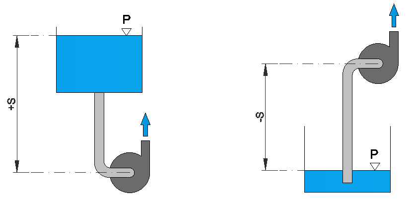
S: Suction head. Vertical distance between suction tank and pump center line. (- ) for operation under suction lift conditions and (+) for operation under flooded suction conditions.

H: Head loss for the maximum flow in pipes, bends and valves on the suction side due to friction.

www.caetool.com

Pipe pressure drop

Pipe pressure drop

Darcy friction factor formulae

Neutrium – Theory


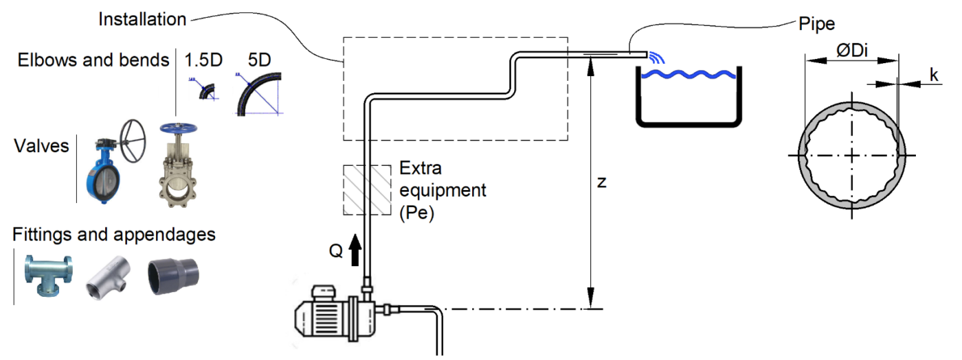
This calculator performs Pressure Drop Calculations for pipework. Additionaly, related parameters such as Reynolds, fluid velocity, average residence time, etcetera are presented. The Pressure Drop calculation takes into account other components as well. It requests the user for input about bends, elbows and other appendages/equipment components, which induce extra pressure loss. The program represents the total resistance in terms of equivalent pipe length values.

www.caetool.com

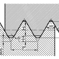
Thread types

Thread types

SymbolAngleParallel/taperedStandardDescriptionApplication
A/B60°ParallelDIN 4503, ISO 1222Tripod connection threadConnections to photografic equipment.
ACME-C29°ANSI B1.5 (1977)Acme thread centralizing
ACME-G29°ANSI B1.5 (1977)Acme thread general purpose
AMO55°ANSI B1.11 (1958)American standard microscope objective thread
ANPT60°MIL-P-7105Aeronautical national form taper pipe thread
API60°American national taper form thread for petroleum installations
BA47°30'BS93 (1951)British association thread
BSC60°BS811 (1950)British norm thread for bicycles
BSF55°ParallelBS84 (1956)Whithworth fine thread
BSW55°ParallelBS84 (1956)Whithworth coarse thread
E-DIN 40400, DIN 49612, DIN 49610, DIN 49625Edison form threadElectrical thread.
EG M60°ParallelDIN 8140-2Metric ISO thread for helical coil wire screw thread insertsFor wire thread inserts.
EG-UNC60°ParallelMS 33537Unified coarse thread series for helical coil wire screw thread inserts
EG-UNF60°ParallelASME B18.29.1Unified fine thread for helical coil wire screw thread inserts
FG60°ParallelDIN 79012Bicycle threadFor cycles and motor-scooters.
G55°ParallelDIN ISO 228, DIN 6630Pipe parallel ISO threadFor pressure tight joints are not made on the thread. External and internal pipe thread. Packaging; external thread for barrels.
G55°ParallelBS2779 (1973)Pipe whitworth thread (BSP)parallel
GfTaperedDIN 4930Round tapered threadTubes and tunneling
Gg60°Tapered (1:16)DIN 4941Tapered threadFor drill pipes in water and rock drilling, mining.
Gg30°-30°Tapered (1:4)DIN 20314Tapered threadFor drill pipes in water and rock drilling, mining.
GL30°-60°ParallelDIN 168-1Cylindrical round threadFor glass containers.
Glasg30°-50°ParallelDIN 40450Glasg thread for glassElectric industry: glass fittings, protection glasses.
HA-HBDIN 58810Bone screw threadFor surgical implants, external and internal thread.
KT20°ParallelDIN 6063Trapezoidal threadPreferably for packages made of plastics.
LN60°ParallelLN 9163, EN 2158ISO Metric thread for aviationAviation and aerospace.
M60°ParallelDIN 13, DIN 14, ISO 68, DIN 6630, LN 9163, DIN 2510Metric coarse ISO threadGeneral engineering, watches, fine work, packaging; external thread for barrels, aviation, aerospace and bolted connections with reduced shank.
M60°Tapered (1:16)DIN 158Taper metric ISO threadPlugs and grease nipples.
MF60°ParallelDIN 13, DIN EN 60423Metric fine ISO thread
MFS60°ParallelDIN 8141-1ISO Metric thread for tight fit
MJ60°ParallelDIN ISO 5855Metric ISO thread for aeronauticsAviation and aerospace.
N60°ANSI B1.1 (1960)American national 8-12-16 TPI pitch series (8N, 12N, 16N)
N-BUTT45°+5°ANSI B1.9 (1973)American BUTTRESS thread
NC60°ANSI B1.1 (1960)American national coarse thread series
NEF60°ANSI B1.1 (1960)American national extra fine thread series
NF60°ANSI B1.1 (1960)American national fine thread series
NGO60°ANSI/ASME-B1.20.1 (1983)National gas outlet thread (specify RH or LH)
NGS60°ANSI/ASME-B1.20.1 (1983)National gas straight thread
NGT60°ANSI B57.1 (1977)National gas taper thread (see also SGT)
NH60°ANSI B2.4 H28 (1966)American national firehouse and hose coupling thread
NPS60°American standard straight pipe thread NSPC & NPSM
NPSC60°ANSI/ASME-B1.20.1 (1983)American standard straight pipe thread in pipe couplings (marked NPS)
NPSF60°ANSI B1.20.3 (1976)Dryseal American standard internal straight pipe thread (fuel)
NPSH60°ANSI/ASME-B1.20.1 (1983)American standard straight pipe thread for hose couplings
NPSI60°ANSI B1.20.3 (1976)American standard intermediate internal straight pipe thread
NPSL60°ANSI/ASME-B1.20.1 (1983)American standard straight pipe thread for loose-fitting mechanical joints
NPSM60°ANSI/ASME-B1.20.1 (1983)American standard straight pipe thread for free-fitting mechanical joints
NPT60°Tapered (1:16)ANSI/ASME-B1.20.1 (1983)American standard tapered pipe thread For threads with dryseal material.
NPTF60°Tapered (1:16)ANSI B1.20.3 (1976)American standard tapered pipe thread (fuel)For threads without dryseal material.
NPTR60°ANSI/ASME-B1.20.1 (1983)American standard taper pipe thread for railing joints (tap market NPT)
NS60°ANSI B1.1 (1960)American national thread special pitches
Pg80°ParallelDIN 40430Steel electrical conduit threadFor electric installations.
PTF60°ANSI B1.20.1 (1976) Dryseal SAE short taper pipe thread
R55°ParallelDIN 259Pipe parallel whitworth threadFor pressure tight joints are not made on the thread. Piping, do not use in new designs.
R55°Tapered (1:16)BS21 (1985), DIN EN 10226-1, ISO 7-1, DIN 2999, DIN 3858External dryseal pipe taper thread (BSPT)Tapered Whitworth pipe thread where pressure-tight joints are made on the threads.
Rc55°Tapered (1:16)BS21 (1985), DIN EN 10226-1, ISO 7-1Internal dryseal pipe taper thread (BSPT)Tapered Whitworth pipe thread where pressure-tight joints are made on the threads.
Rd30°ParallelDIN 405, DIN 20400, DIN 15403, DIN 7273Rounded threadGeneral, for mining industry, for lifting hooks, for steel sheet items and related joints.
RMS55°ParallelDIN 58888RMS-threadObjective for microscope.
Rp55°ParallelDIN 2999, DIN 3858Internal dryseal parallel threadInternal thread for pipes and fittings.
Rp55°ParallelBS21 (1973), DIN EN 10226-1, ISO 7-1Pipe parallel thread (BSPP)Cylindrical Whitworth pipe thread where pressure-tight joints are made on the threads.
S30°+3°ParallelDIN 513, DIN 20401Saw form threadGeneral. Mining industry.
S45°ParallelDIN 2781Saw form threadFor machine tools, hydraulic presses.
S105°Tapered (7°30')DIN 71412Self forming taper external threadTaper lubricating nipple. Similar to DIN 158 but 105° thread angle.
SBManufacturers stovebolt standards thread
SGT60°ANSI B57.1 (1977)Special gas taper thread
SPL-PTF60°ANSI B1.20.3 (1976)Dryseal special taper pipe thread
ST60°ParallelDIN 7970, DIN EN ISO 1478Sheet metal screw threadFor tapping screws.
STI60°Special thread for helical coil wire screw thread inserts
STUB-ACME29°ANSI B1.8 (1977)Stub Acme thread
Tr30°ParallelDIN 103, DIN 380, DIN 263, DIN 6341, DIN 30295Trapezoidal threadGeneral, for rail vehicles, for collet chucks.
UN60°ANSI B1.1 (1982)Unified 8-12-16 TPI pitch series
UN-860°ASME B1.1Unified thread for special diameters and pitches
UNC60°ANSI B1.1 (1982)Unified coarse thread series
UNEF60°ANSI B1.1 (1982)Unified extra fine thread series
UNF60°ANSI B1.1 (1982)Unified fine thread series
UNJ60°BS 4048 (1978)Unified constant pitch with a 0,15011P to 0,18042P controlled root radius
UNJC60°BS 4048 (1978), ASME B1.15Unified coarse thread with a 0,15011P to 0,18042P controlled root radius
UNJEF60°BS 4048 (1978)Unified extra fine thread with a 0,15011P to 0,18042P controlled root radius
UNJF60°BS 4048 (1978), ASME B1.15Unified fine thread with a 0,15011P to 0,18042P controlled root radius
UNM60°ASA B1.10 (1958)Unified miniature thread series
UNS60°ANSI B1.1 (1982)Unified thread special pitches
V60°60° "V" thread with truncated crest and root(flatted to the user's specifications)
Vg60°ParallelDIN 7756Valves threadValves for tires.
W55°ParallelDIN 477Parallel whitworth threadCylindrical thread for side connections.
W keg55°Tapered (3:25)DIN 477, DIN EN 144-1, DIN EN 629-1, DIN EN ISO 11116-1Tapered thread for screw socketsGas cylinders, thread for side nozzles.

www.caetool.com

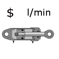
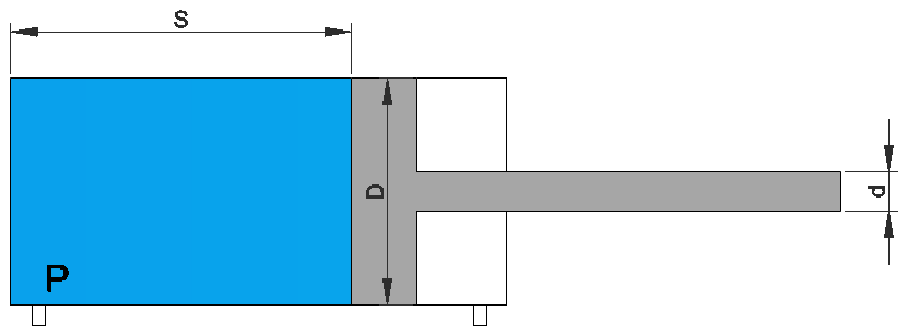
Cylinder air consumption

Cylinder air consumption

This calculator is valid for simple and double effect. For simple effect the value provide by the calculator  has to be divided by 2.
Leakage is not taken into the calculator.

www.caetool.com

Centrifugal force

Centrifugal force

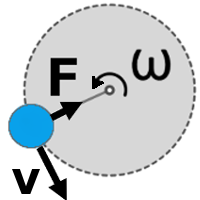
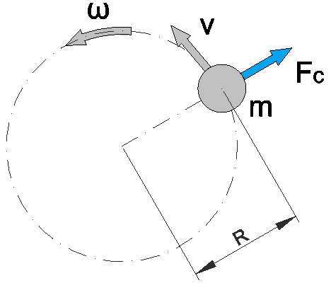
Centrifugal force is the inertia force that arises in each rotating object. It is only required in a rotating reference frame – or, in other words, when we look at the system from the point of view of the object in motion.

F=mcdot frac{v^{2}}{R}

F: the force

m: the mass of the object

v: the velocity

R: the radius

www.caetool.com

Index of protection

Index of protection

Standards organisations

IEC – International Electrotechnical Commission, publishes international standards for all electrical, electronic, and related technologies. www.iec.ch

NEMA – National Electrical Manufacturers Association, a U.S. trade association sets ratings for environmental sealing. www.nema.org

The IP Rating System describes the ‘degree of protection’ as defined by the International Electrotechnical Commission standard 60529 (IEC60529). IP stands for International Protection, frequently referred to as ‘Ingress Protection’. The degree of protection as defined by the IEC is used to describe:

  • Protection offered to people against hazardous parts inside an enclosure.
  • Protection of equipment inside the enclosure against the intrusion of solids.
  • Protection of equipment inside the enclosure against the ingress of liquids.

The IP code designation consists of the letters IP followed by two numerals, and is sometimes followed by optional letters. The first number is a measure of how well the enclosure can prevent an invasion by solids. The second number indicates the degree of protection against liquids of various pressures, directions and volumes.

The IP rating system does not cover condensation, fungus and harmful vapour so assumptions should not be made that a highly rated switch will be protected.

NEMA considers numerous requirements including corrosion resistance, effects of icing, gasket aging and oil resistance and coolant effects. It is possible to say that a NEMA Type is equivalent to an IP rating but an IP rating is not equivalent to a NEMA Type. The IP code only address requirements for the protection of people, the ingress of solids and the ingress of water. The NEMA Types consider these and also numerous other requirements including: 

  • Construction requirements
  • Door and cover securement
  • Corrosion resistance
  • Effects of icing
  • Gasket aging and oil resistance
  • Coolant effects


IP69K

German standard DIN 40050-9 extends IEC 60529 with an additional rating for environmental sealing – IP69K, for high-pressure, high-temperature wash-down applications. Devices must not only be dust tight (IP6X), but also able to withstand high-pressure and steam cleaning. The test is very strict: 80°C water is sprayed through a nozzle at pressures of 8–10 MPa (80–100 bar) and a flow rate of 14–16 Litres/min. The nozzle must be held 10–15 cm from the tested device at angles of 0°, 30°, 60° and 90° for 30 seconds each. The test device sits on a turntable that rotates once every 12 seconds (5 rpm). The IP69K test specification was initially developed for road vehicles, especially construction vehicles and those that need regular intensive cleaning, but also finds use in other intensely hygienic applications (e.g. food industry).

NEMA

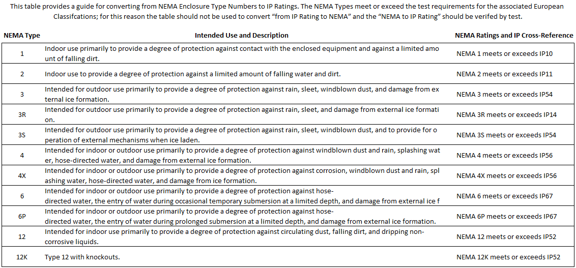
In the United States, the National Electrical Manufacturers Association sets the requirements for environmental sealing and its standards are widely used throughout North, Central and South America. The NEMA Standards Publication 250 – 2008 (previously 250 – 2003; 250 – 1997) “Enclosures for Electrical Equipment (1000 Volts Maximum)” defnes enclosures according to their type from 1 to 13. Detailed information on some of the types relevant to HMI components are shown in Table 3.

www.caetool.com

Absolute roughness

Absolute roughness

Pipe MaterialAbsolute roughness k (mm)
Aluminum new0,001-0,002
Brass0,015
Brass new0,001-0,002
Cast iron new0,25-0,8
Cast iron slightly rusted1,5
Cast iron very rusted3
Cast iron with bitumen layer0,2
Copper0,015
Copper new0,001-0,002
Epoxy, vinyl ester and isophthalic pipe0,005
Flexible rubber tubing smooth0,006-0,07
Glass0,015
Lead0,015
Lead new0,001-0,002
Ordinary concrete0,3-1
PVC and Plastic pipes0,0015-0,007
Rough concrete0,3-5
Sheet or asphalted cast iron0,01-0,015
Smoothed cement0,3
Stainless steel electropolished0,0001-0,0008
Stainless steel turned0,0004-0,006
Stainless steel, bead blasted0,001-0,006
Steel pipe after longer use0,2
Steel pipe galvanised0,15
Steel pipe new0,04
Steel pipe slightly rusted0,4
Steel pipe very rusted3,35
Stretched steel0,015
Weld steel0,045
Worn cast iron0,8-1,5

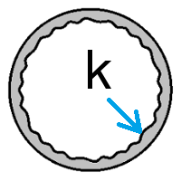
Absolute Roughness (k) is a measure of pipe wall irregularities. The absolute roughness has dimensions of length and is usually expressed in millimeter (mm) or feet (ft). Absolute Roughness is usually defined for a material and can be measured experimentally. Absolute roughness is important when calculating pressure drop particularly in the turbulent flow regime.

For each pipe material either a single pipe roughness value or a range of roughness values is normally provided by the manufacturer. The roughness value, usually denoted as e or k, is used in the calculating the relative roughness of a pipe against the size of its diameter.

www.caetool.com

Slings for machinery lifting

Slings for machinery lifting

lift-it

mennens

certex

lift-tex

haklift

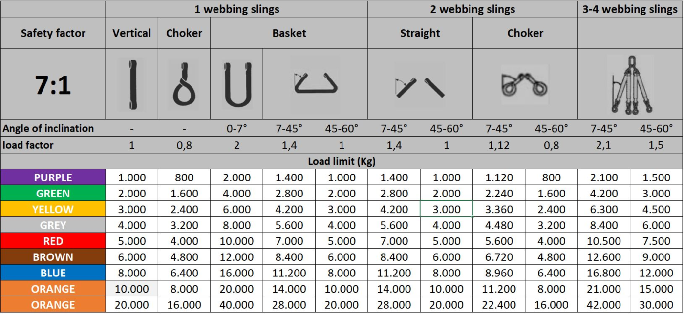
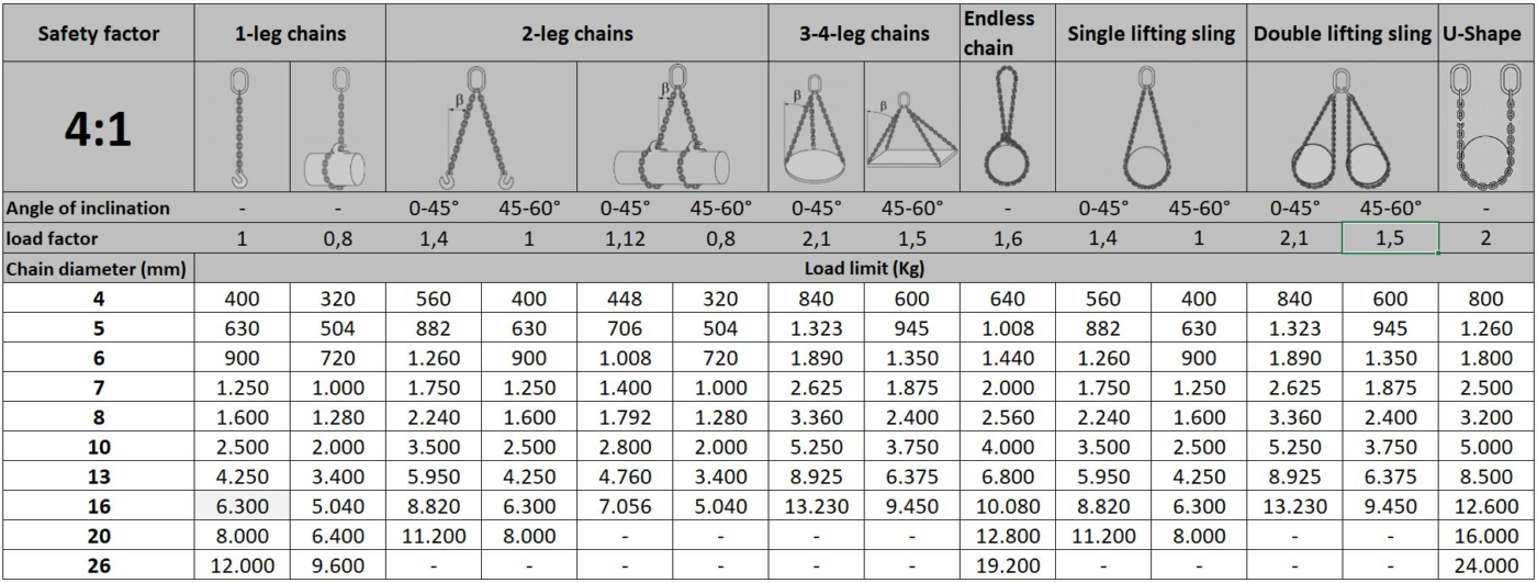
The minimal Safety factor must be at least equal to:

7:1 for webbing and round slings

4:1 for accessories made of steel

5:1 for the remaining components

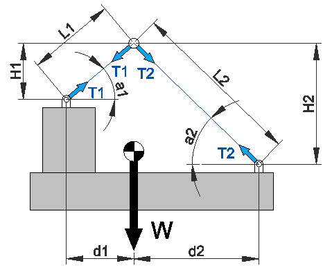
Recommendations of use:

  • Never slide slings under a load. Never leave a load laying on a sling.
  • Never knot slings or never use twisted slings.
  • Protect from any sharp edges.
  • Never use knotted, cut or damaged slings without tags.
  • Check the weight of the load. Never overload.
  • Use slings in arrange of temperature -40°C to +100°C.
  • Reference to the standards: EN 1492-1, EN 1492-2, DIN 61360,  CEN Norm.

Eye opening angle

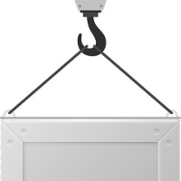
The minimum length for the eyes is fixed by standard EN 1492-1 to 3 times the width of the sling for widths up to 150mm; 2,5 times for width above 150mm. These lengths have been fixed to respect an angle usage between 10° to 20° when using the slings. An excessive eye opening angle will open the sling and a small eye opening angle will generate a bending stress at the lifting axis.

www.caetool.com

Mass moments of inertia calculator

Mass moments of inertia calculator

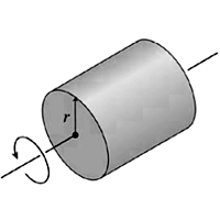
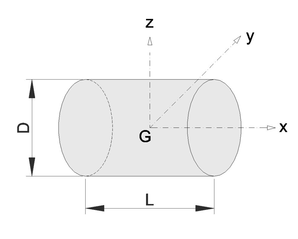
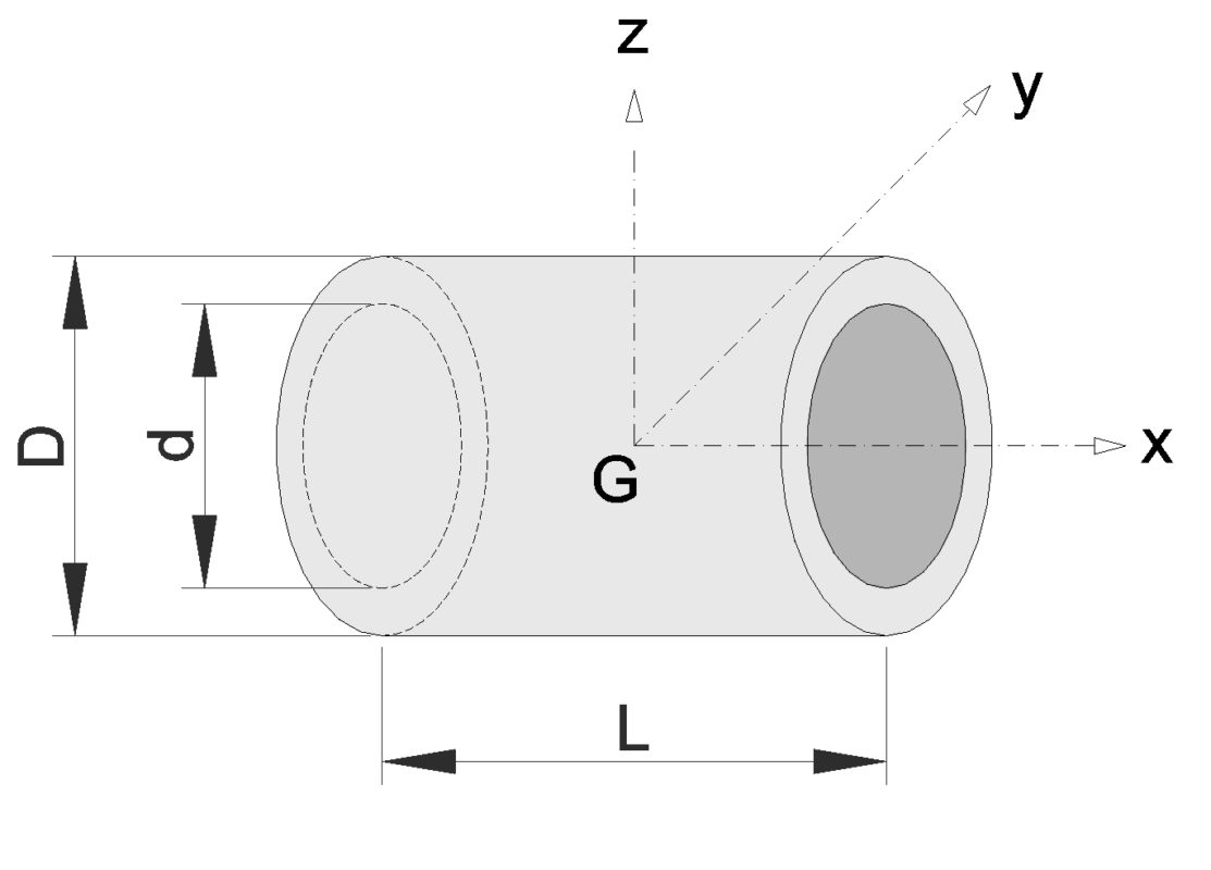
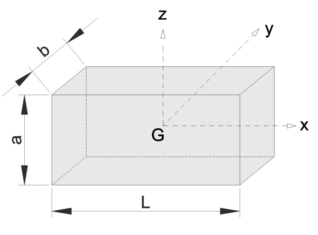
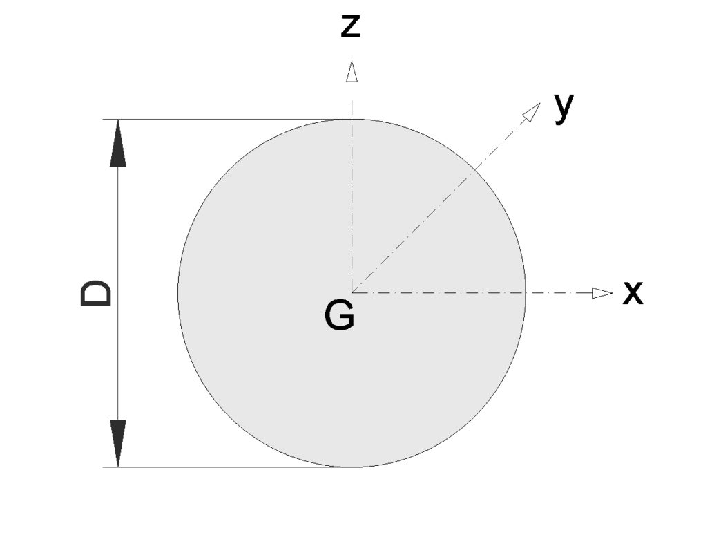
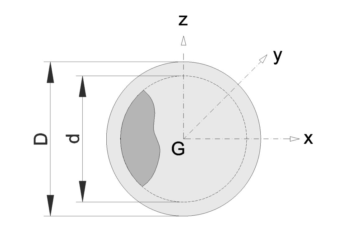
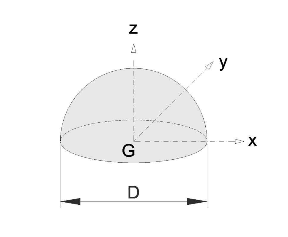
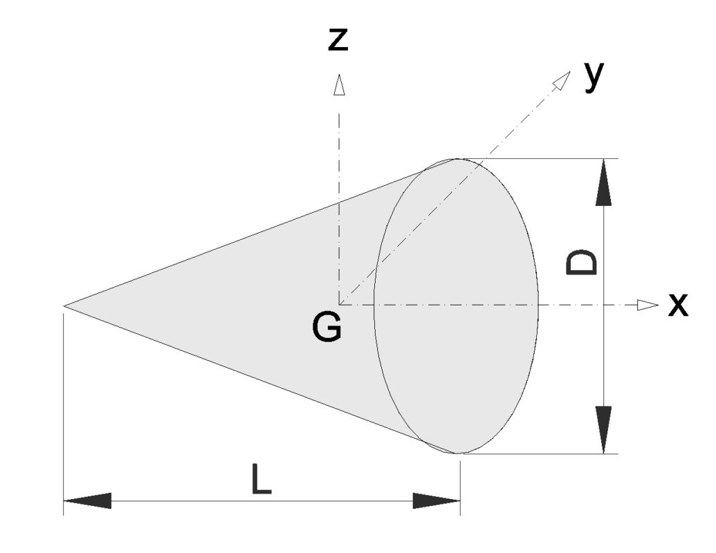
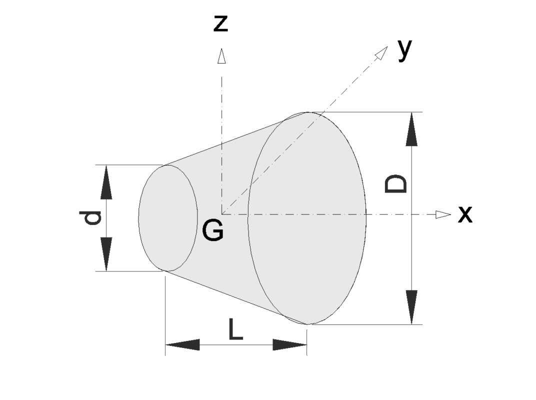
The moment of inertia, otherwise known as the angular mass or rotational inertia,  is a measure of an object’s resistance to change in rotation direction. Moment of Inertia has the same relationship to angular acceleration as mass has to linear acceleration.

  • Moment of Inertia of a body depends on the distribution of mass in the body with respect to the axis of rotation

For a point mass the Moment of Inertia is the mass times the square of perpendicular distance to the rotation reference axis and can be expressed as

I = m r2                 

Where

I = moment of inertia (kg m2)

m = mass (kg)

r = distance between axis and rotation mass (m)

www.caetool.com

Friction coefficients

Friction coefficients

Material 1Material 2Static dryStatic lubricatedDynamic dryDynamic lubricated
SteelSteel0.50.10.40,1-0,05
SteelCast iron0.20.10.180,1-0,05
SteelCu-Sn alloy0.20.10.10,06-0,03
SteelPb-Sn alloy0.150.10.10,05-0,03
SteelPolyamide0.30.150.30,12-0,03
SteelPTFE0.040.040.040.04
Steelfriction lining0.60.30.550,3-0,2
SteelWood0.550.10.350.05
WoodWood0.50.20.30.1
Cast ironCu-Sn alloy0.250.160.20.1
RubberCast iron0.50.45
Rolling elementSteel0,003-0,001
AluminumAluminum1,05-1,350.31.4
AluminumMild steel0.610.47
BrassCast iron0.3
BronzeCast iron0.22
Cast ironCast iron1.10.150.07
CopperStainless steel (304)0.230.21
GlassGlass0,9-10,1-0,60.40,09-0,12
GlassMetal0,5-0,70,2-0,3
GraphiteGraphite0.10.1
GraphiteSteel0.10.1
NylonNylon0,15-0,25
PolystyrenePolystyrene0.50.5
PolystyreneSteel0,3-0,350,3-0,35
SteelBrass0.350.19
Mild steelBrass0.510.44
Mild steelCast iron0.180.230.13
TeflonSteel0.040.040.04
Titanium AlloyAluminium Alloy0.410.38
Titanium AlloyTitanium Alloy0.360.3
Titanium AlloyBronze0.360.27

The friction coefficient depend on several factors: contact pressure, surface roughness, temperature, sliding velocity, type of lubricant  and level of contamination.
Static coefficients of friction are higher than the dynamic or kinetic values. 

www.caetool.com